Cutting insert and a milling tool

a technology of cutting inserts and milling tools, applied in the field of cutting inserts, can solve problems such as inability, and achieve the effect of efficient us

Active Publication Date: 2013-05-23
SANDVIK INTELLECTUAL PROPERTY AB
View PDF33 Cites 57 Cited by
  • Summary
  • Abstract
  • Description
  • Claims
  • Application Information

AI Technical Summary

Benefits of technology

[0007]The object of the present invention is to overcome the problems discussed above and to provide an in

Problems solved by technology

With a standard negative square cutting insert, it is not possible to obtain a unique axial and radial position of the cutting insert in a cutter body tha

Method used


Image

  • Cutting insert and a milling tool
  • Cutting insert and a milling tool
  • Cutting insert and a milling tool

Examples


first embodiment

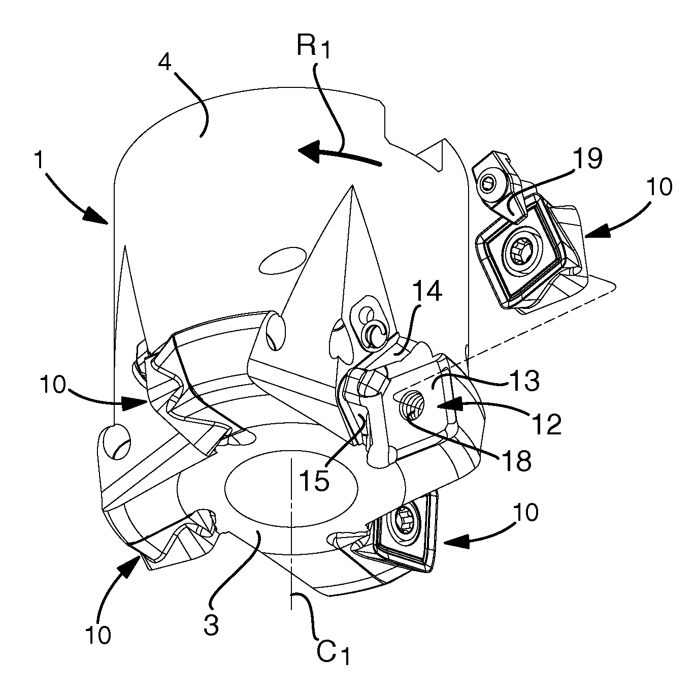
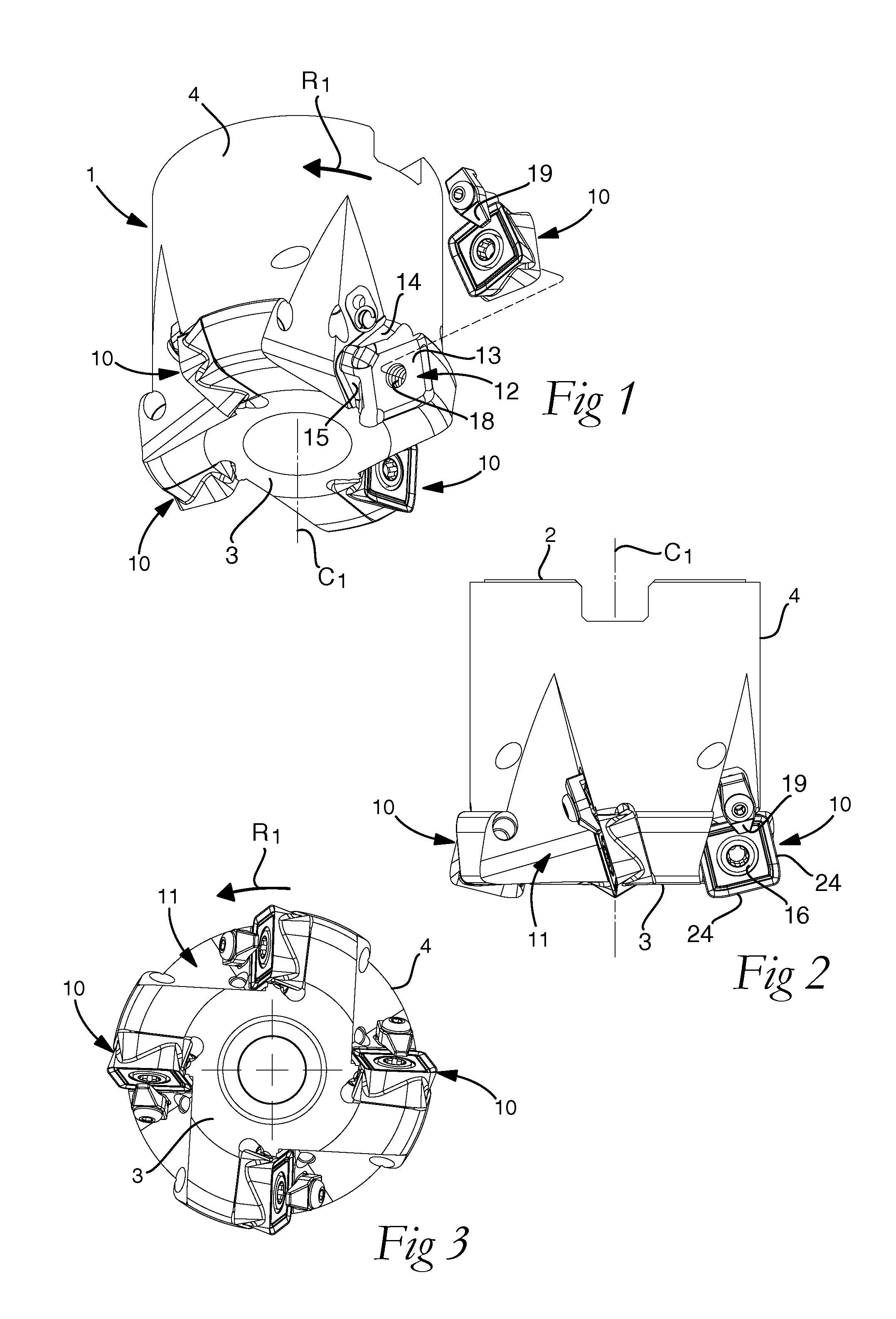
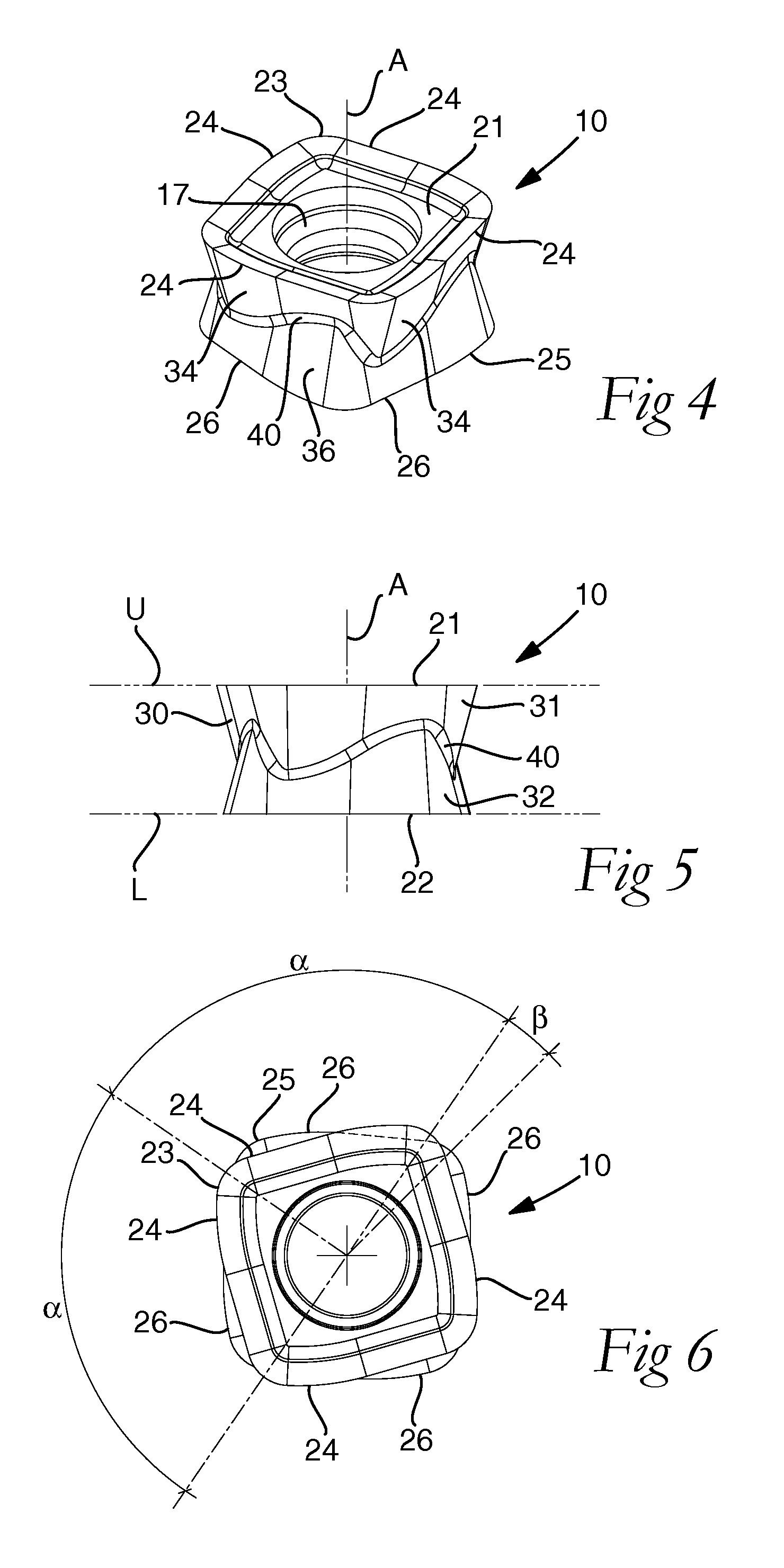
[0051]the cutting insert 10, mounted in the cutter body 1 in FIGS. 1 to 3, is disclosed more closely in FIGS. 4 to 6. The cutting insert 10 comprises an upper side 21 defining an upper extension plane U, and a lower side 22 defining a lower extension plane L being parallel with the upper extension plane U. A centre axis A extends perpendicularly through the upper extension plane U and the lower extension plane L. The centre hole 17 extends through the upper side 21 and the lower side 22 in parallel and concentrically with the centre hole 17.

[0052]An upper cutting edge 23 extends around the upper side 21 and forms four upper cutting edge portions 24. Each upper cutting edge portion 24 has a length corresponding to a determined angle a with respect to the centre axis A. A lower cutting edge 25 extends around the lower side 22 and forms four lower cutting edge portions 26. Each lower cutting edge portion 26 also has a length corresponding to said determined angle a with respect to the ...

fourth embodiment

[0068]FIGS. 13 to 15 disclose the cutting insert 10 which differs from the previous embodiments in that the cutting insert 10 has five upper cutting edge portions 26 and five lower cutting edge portions 26, and thus an overall pentagonal shape, wherein the determined angle α is 72°. The transition area 40 has an irregular wave-like shape.

[0069]FIGS. 16 to 18 disclose a fifth embodiment of the cutting insert 10 which differs from the first and second embodiments in that the cutting insert 10 has a plane upper side 21 and a plane lower side 22. Furthermore, in contrast to the first and second embodiments, the cutting edge portions 24, 26 are straight between the slightly bended ends. Moreover, in the fifth embodiment, the acute angle formed between the each upper side surface 34 and the upper extension plane U with respect to the associated upper cutting edge portion 24, and each lower side surface 36 and the lower extension plane L with respect to the associated lower cutting edge po...


PUM

PropertyMeasurementUnit
Fractionaaaaaaaaaa
Lengthaaaaaaaaaa
Angleaaaaaaaaaa

Abstract

A cutting insert for face milling and ramping includes an upper side defining an upper extension plane, a lower side defining a lower extension plane parallel with the upper extension plane, and an edge side extending around the cutting insert. A centre axis extends perpendicularly through the upper and lower extension planes. An upper cutting edge forms four upper cutting edge portions having an identical length corresponding to a determined angle with respect to the centre axis. A lower cutting edge forms four lower cutting edge portions (26), having an identical length corresponding to the determined angle with respect to the centre axis. Each upper cutting edge portion is displaced angularly with respect to the centre axis in relation to one of the lower cutting edge portions with a displacement angle being greater than zero and less than the determined angle.

Description

TECHNICAL FIELD OF THE INVENTION[0001]The present invention refers to a cutting insert configured for chip-removing machining and for being mounted in a cutter body for face milling and ramping of a workpiece according to the preamble of claim 1. Such a cutting insert is disclosed in US 2010 / 0303563. The present invention also refers to a milling tool according to claim 15, comprising a cutter body and a number of such cutting inserts.[0002]In the cutting insert of the present invention, the geometries, including chip forming configurations, are located on the upper side and the lower side of the cutting insert. This is in contrast to prior art cutting inserts having the geometries located on the periphery of the cutting insert, as shown in US 2010 / 0129166, for instance.[0003]US 2010 / 0303563 discloses a cutting insert configured for milling operations, such as face milling, slot milling, plunge milling and ramping. The known cutting insert comprises an upper side defining an upper e...

Claims


Application Information

Patent Timeline
IPC IPC(8): B23C5/20B23C5/06
CPCB23C5/207B23C5/06B23C2200/125B23C5/109B23C5/2221B23C5/2247Y10T407/1924B23C2200/0444B23C2200/0455B23C2200/0477B23C2200/128Y10T407/23B23B2200/3681B23C5/202B23C5/2213B23C5/20B23C5/22B23B27/16
Inventor JAEGER, SEBASTIENHUTEAU, PATRICK
Owner SANDVIK INTELLECTUAL PROPERTY AB
Why Eureka
Try Eureka