Wind turbine blade

Active Publication Date: 2013-05-23
BLADE DYNAMICS LTD
View PDF5 Cites 31 Cited by
  • Summary
  • Abstract
  • Description
  • Claims
  • Application Information

AI Technical Summary

Benefits of technology

[0021]Preferably, the end of each shear web is substantially perpendicular (when viewed in cross section in an axial plane running parallel to the spar caps) to the axial direction such that the ends of the shear webs support one another. Also preferably, there is no double scarf joint between the shear webs. This provides a simplified yet robust construction where the connection pieces are confined only to the spar caps and the webs are mutually supporting.
[0022]The connection piece may be fixed in place by bonding. In this case, the connection piece is provided as a single piece. This is preferably a pre-cured part. For the reasons mentioned above, the ease of handling of the connection piece and the direction of movement will not unduly disturb the adhesive in the joint.
[0023]Alternatively, the connection piece may be formed in situ as a n

Problems solved by technology

In particular, neither of the spar segments has the protruding

Method used


Image

  • Wind turbine blade
  • Wind turbine blade
  • Wind turbine blade

Examples


Example

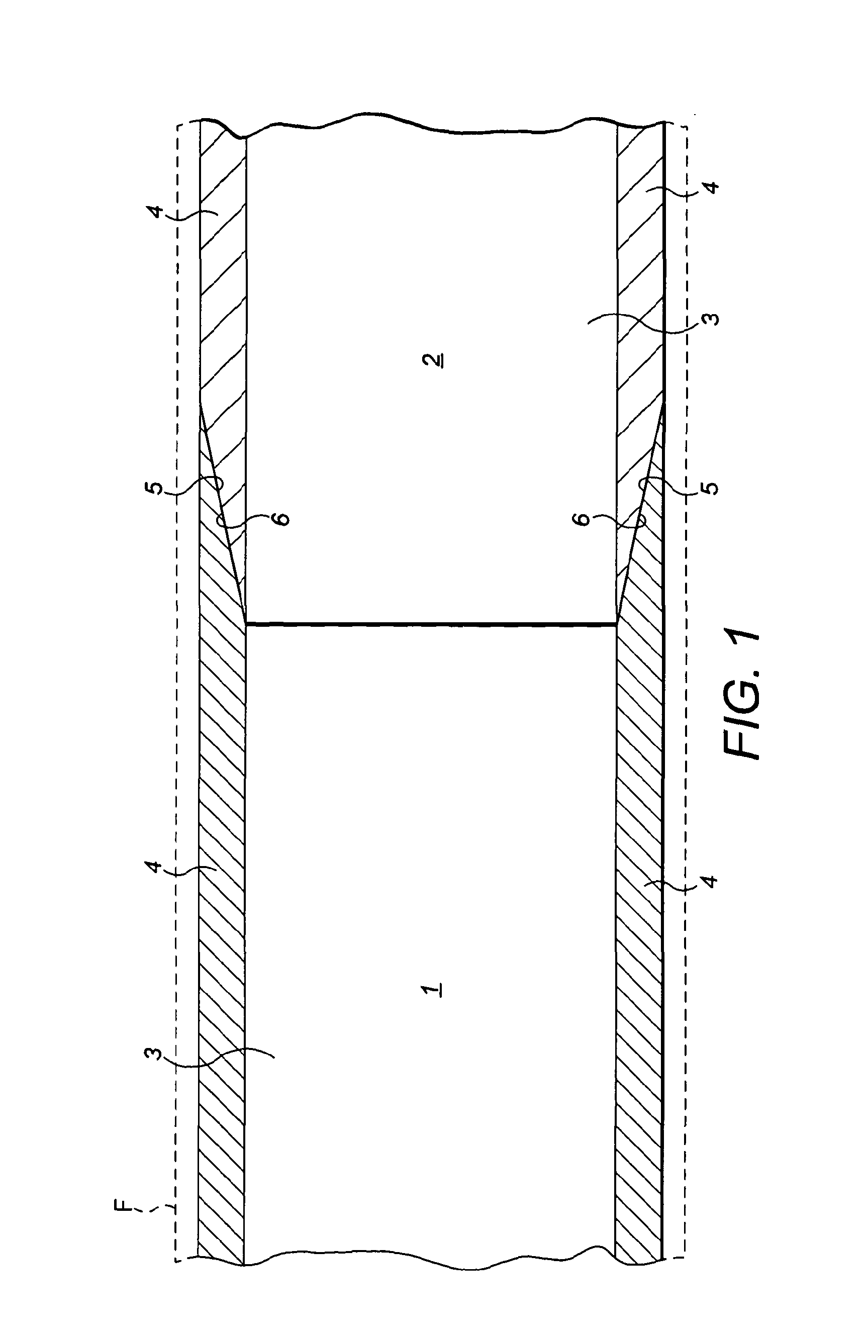
[0044]The spar comprises two spar segments 7 which are essentially the same in structure as the second spar segment 2 shown in FIG. 1. Each has a shear web 3, made of the multi-axial material and spar caps 4 are provided on either side which are formed predominantly of a uni-axial material which are preferably formed as pulltrusions, but could also be made from prepreg, laminations or other pre-forms known in the art which give cost effective spar caps with good mechanical properties.

[0045]Further details of the construction and materials of the spar sections are disclosed in our own earlier WO 2009 / 034291.

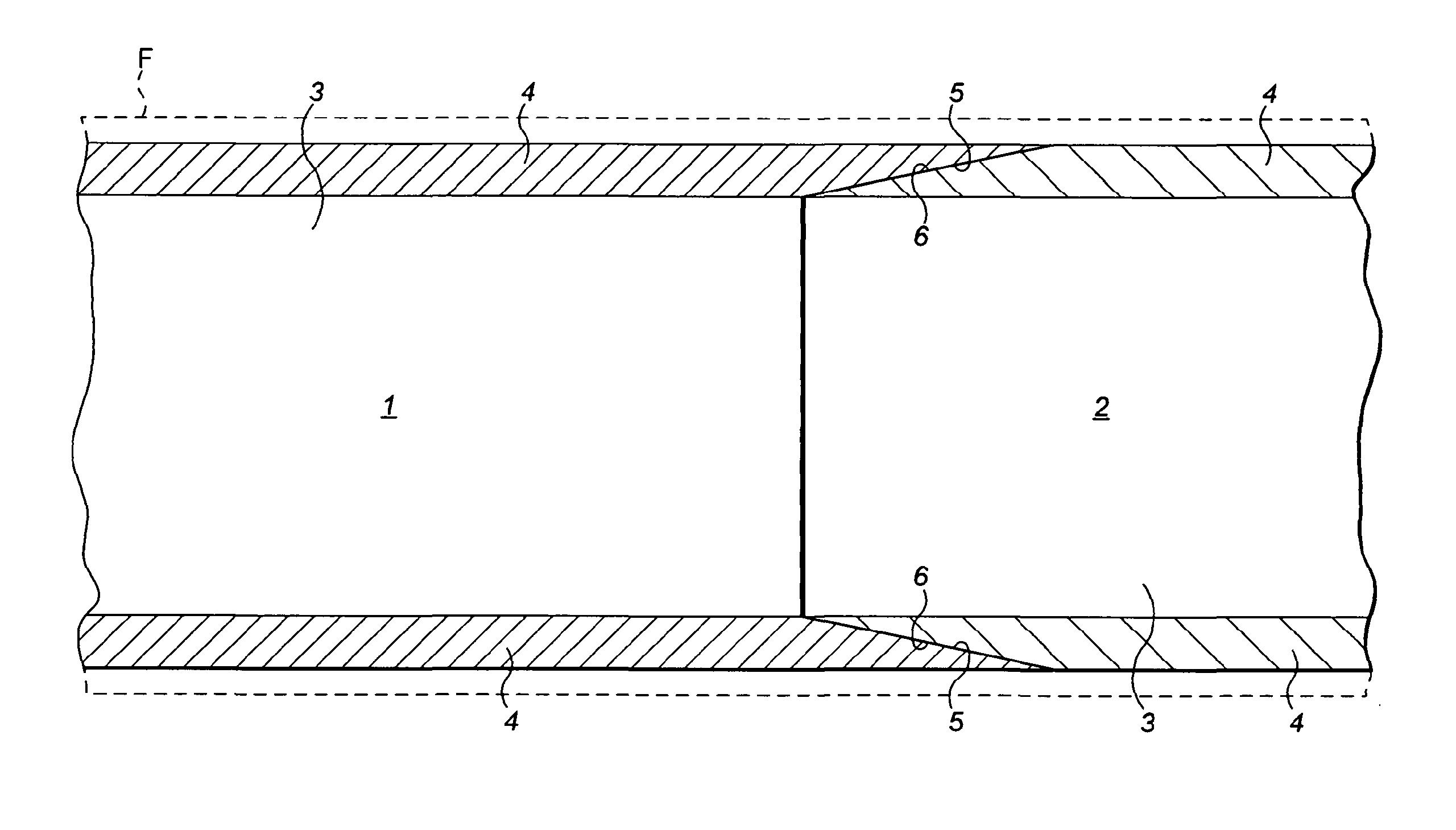
[0046]At the end adjacent to the joint, each of the spar caps 4 has a tapered surface 6 as described above in relation to FIG. 1.

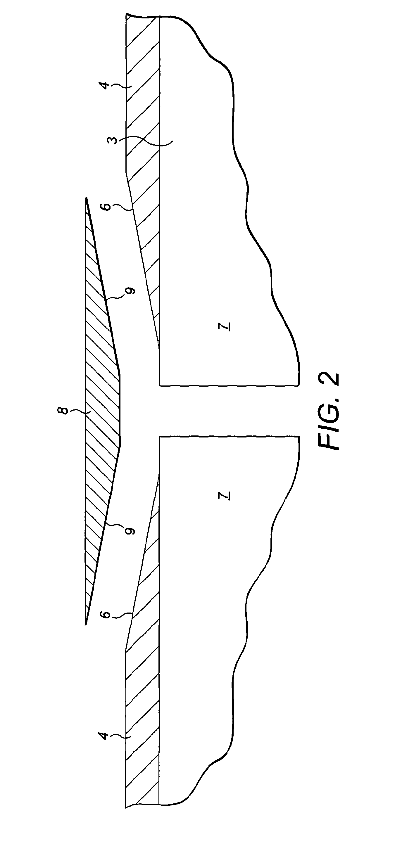
[0047]A pair of connection pieces 8 have a width and depth which corresponds to the width and depth of the adjacent spar caps 4 and have inclined faces 9 which correspond to the inclined faces 6 of the spar caps 6 so that, in use, as shown in FIG. 3, the...


PUM


Abstract

A wind turbine blade comprising an aerodynamic fairing supported along at least a portion of its axial length by a spar (12). The spar comprises at least two spar segments (12) joined end-to-end at an interface (9), each spar segment comprising a shear web (3) with a spar cap (4) on each side. The outer face (6) of each spar cap tapers inwardly towards the interface such that its depth is reduced towards the interface creating a recess on each side of the interface formed by the tapered faces of adjacent spar caps. A respective connection piece (8) is sized to fit into each recess. Each connection piece (8) is sized to fit into each recess. Each connection piece (8) being fixed to the tapered faces of adjacent spar caps to form a double scarf joint.

Description

CROSS-REFERENCE TO RELATED APPLICATIONS[0001]This application is a continuation of Patent Cooperation Treaty International Patent Application PCT / GB2011 / 001035, filed Jul. 8, 2011, and entitled “A WIND TURBINE BLADE,” which is incorporated by reference herein in its entirety, and which claims priority to Great Britain Patent Application 1011539.2, filed on Jul. 8, 2010.BACKGROUND OF THE INVENTION[0002]1. Field of the Invention[0003]The present invention relates to a wind turbine blade.[0004]2. Description of the Related Art[0005]There is an increasing trend for longer and longer wind turbine blades. This has led to a recent development whereby each blade is manufactured in a number of sections which are connected end-to-end in order to form the finished blade. The joint between these adjacent sections is critical to the operation of the blade.[0006]Such wind turbine blades generally comprise an aerodynamic fairing supported by a longitudinally extending spar. In any blade consisting...

Claims


Application Information

Patent Timeline
IPC IPC(8): F03D1/06
CPCF03D1/0675F05B2240/302Y10T29/49339Y02E10/721F03D1/0633B29C70/40B29C70/84Y02E10/72
Inventor HAYDEN, PAUL TREVORBEHMER, HARALD
Owner BLADE DYNAMICS LTD
Why Eureka
Try Eureka