Method and system for quadrature error compensation

a quadrature error and compensation technology, applied in the field of gyroscopes or gyroscope devices, can solve the problem that the movement mass deviates from the ideal theoretically stipulated movement direction, and achieve the effect of compact and relatively inexpensive sensors

Active Publication Date: 2013-05-30
MAXIM INTEGRATED PROD INC
View PDF10 Cites 1 Cited by
  • Summary
  • Abstract
  • Description
  • Claims
  • Application Information

AI Technical Summary

Benefits of technology

[0029]The electrodes of the compensation device are advantageously provided to detect and evaluate the drive movement and / or to drive the mass / es. A very compact and relatively inexpensive sensor can therefore be created.

Problems solved by technology

The quadrature error caused, for example, by small design tolerances in production of the sensor and / or non-uniform temperature expansion means that the moving mass deviates from its ideal theoretically stipulated movement direction.
Signals are generated in the detection electrodes because of this, which overlap the signals for detecting accelerations or rotation rates of the sensor and prevent correct detection.

Method used


Image

  • Method and system for quadrature error compensation
  • Method and system for quadrature error compensation
  • Method and system for quadrature error compensation

Examples


Embodiment Construction

[0036]Specific embodiments of the invention can be found in a method and system for quadrature error compensation, for example, in but not restricted to gyroscope devices.

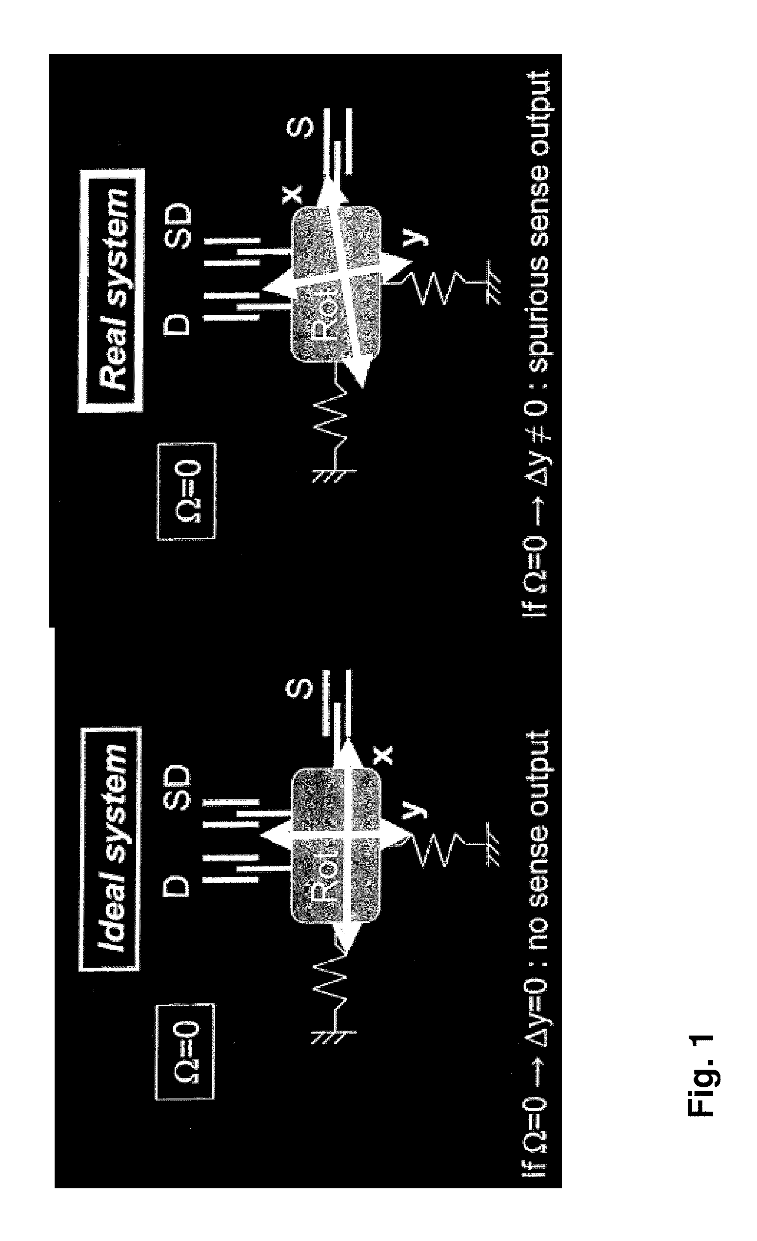
[0037]FIG. 1 is a depiction showing how a quadrature error occurs in a capacitive gyroscope.

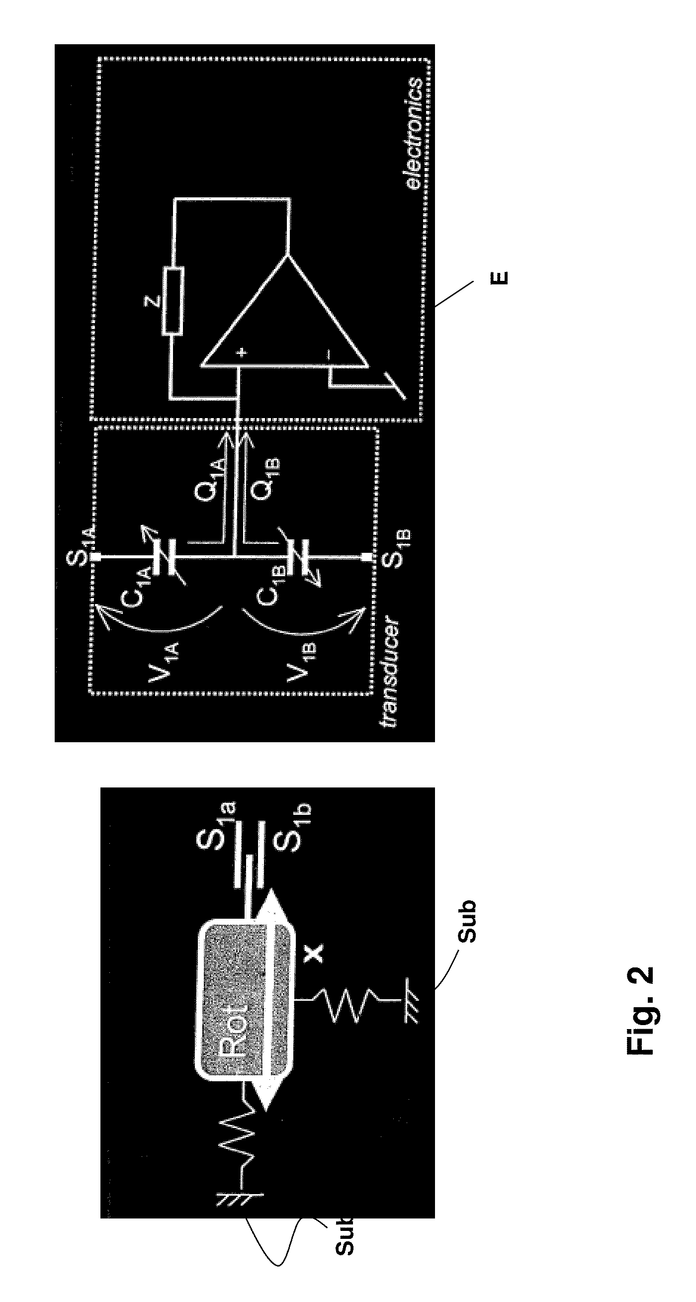
[0038]“Rot” in FIG. 1 denotes the rotor or moving mass, “D” the drive electrodes, “SD” or “S2a” and “S2b” the drive detection electrodes, “S” the detection electrodes, “Ω” the rotation rate, “x” the drive device and “y” the detection device. The rotor “Rot” is mounted to move on a substrate “Sub” by means of springs “F”. The electrodes “D”, “SD” and “S2a” and “S2b” can serve as compensation electrodes, since they can detect the movement of the mass Rot, to which the quadrature error is proportional.

[0039]As is apparent from FIG. 1, an ideal system is present if Ω=0 and Δy=0. No detection output is then present.

[0040]In contrast to this, in a real system, if Ω=0, Δy≠. An interfering detection output signal then occurs.

[0041]F...


PUM


Abstract

The present invention concerns an MEMS sensor and a method for compensation of a quadrature error on an MEMS sensor, which is intended for detection of movements of a substrate, especially accelerations and/or rotation rates. At least one mass arranged on the substrate and mounted to move relative to it is driven by means of drive electrodes. The mass/es execute a movement deviating from the prescribed movement due to a quadrature error. A deflection of the mass/es occurring due to Coriolis force and quadrature error is detected with detection electrodes. It is proposed according to the invention that a capacitance change be detected as a function of drive movement of the mass/es by means of compensation electrodes. A compensation charge dependent on the quadrature error of the MEMS sensor is generated on the compensation electrodes. For compensation, the distorted or incorrect charge generated by the quadrature error in the detection electrodes is compensated with the compensation charge.

Description

CROSS REFERENCE TO RELATED APPLICATIONS[0001]This application claims priority under 35 U.S.C. §119 to European Patent Application No. 11004355.1, filed on May 26, 2011.BACKGROUND[0002]A. Technical Field[0003]Specific embodiments of the invention pertain to gyroscopes or gyroscope devices and / or methods and systems for quadrature error compensation, for example, in gyroscopes or gyroscope devices.[0004]B. Background of the Invention[0005]A problem to be solved exists in gyroscope devices in the occurrence of quadrature errors. A quadrature error, for example, can be an interfering signal superimposed on a useful rotation rate signal.[0006]Quadrature errors are caused by inaccuracies and asymmetries in the geometry of the moving mass of the gyroscope. The amplitude of such a quadrature error can be 10 to 100 times the typical gyroscope full deflections.[0007]The quality of the gyroscope device is influenced by the quadrature error, for example, in the following parameters:[0008]dynami...

Claims


Application Information

Patent Timeline
Patent Type & Authority Applications(United States)
IPC IPC(8): G01P21/00
CPCG01P21/00G01C19/56B81B7/02B81B2201/0242G01C25/005
Inventor CORONATO, LUCACAZZANIGA, GABRIELECAMINADA, CARLOSANTORO, MANUELPRANDI, LUCIANOKONDYLIS, DEMETRE
Owner MAXIM INTEGRATED PROD INC
Why Eureka
Try Eureka