Solar cell and manufacturing method thereof

a solar cell and manufacturing method technology, applied in the field of solar cells, can solve the problems of limited light incidence area and reduced efficiency of solar cells

Inactive Publication Date: 2013-05-30
SAMSUNG SDI CO LTD
View PDF4 Cites 47 Cited by
  • Summary
  • Abstract
  • Description
  • Claims
  • Application Information

AI Technical Summary

Problems solved by technology

Regarding a solar cell, when an electrode electrically connected to an emitter and a substrate is positioned on a sunlight incidence plane of the solar

Method used


Image

  • Solar cell and manufacturing method thereof
  • Solar cell and manufacturing method thereof
  • Solar cell and manufacturing method thereof

Examples


Embodiment Construction

[0027]Korean Patent Application No. 10-2011-0124527, filed on Nov. 25, 2011, in the Korean Intellectual Property Office, and entitled: “Solar Cell and Manufacturing Method Thereof,” is incorporated by reference herein in its entirety.

[0028]Example embodiments will now be described more fully hereinafter with reference to the accompanying drawings; however, they may be embodied in different forms and should not be construed as limited to the embodiments set forth herein.

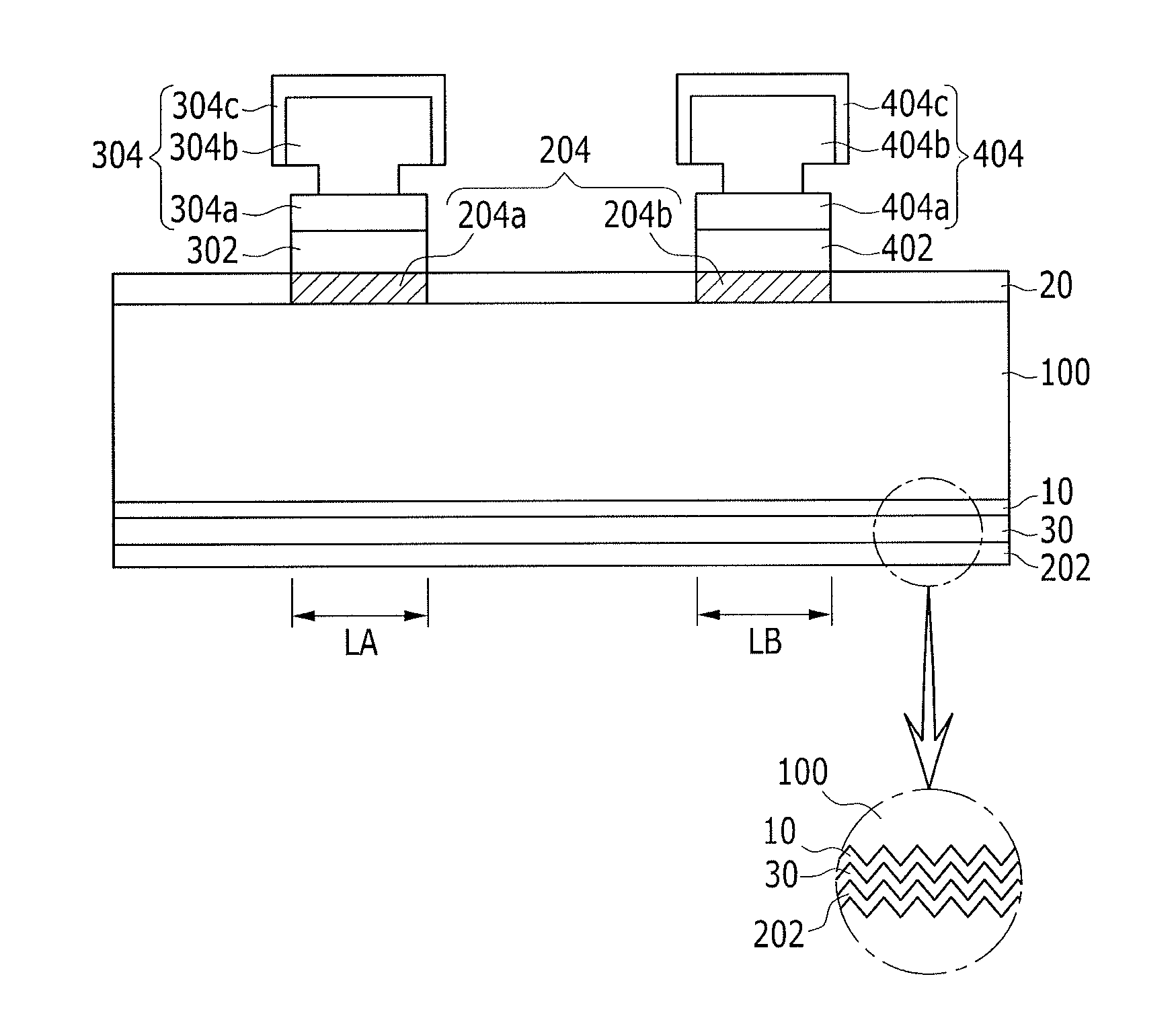
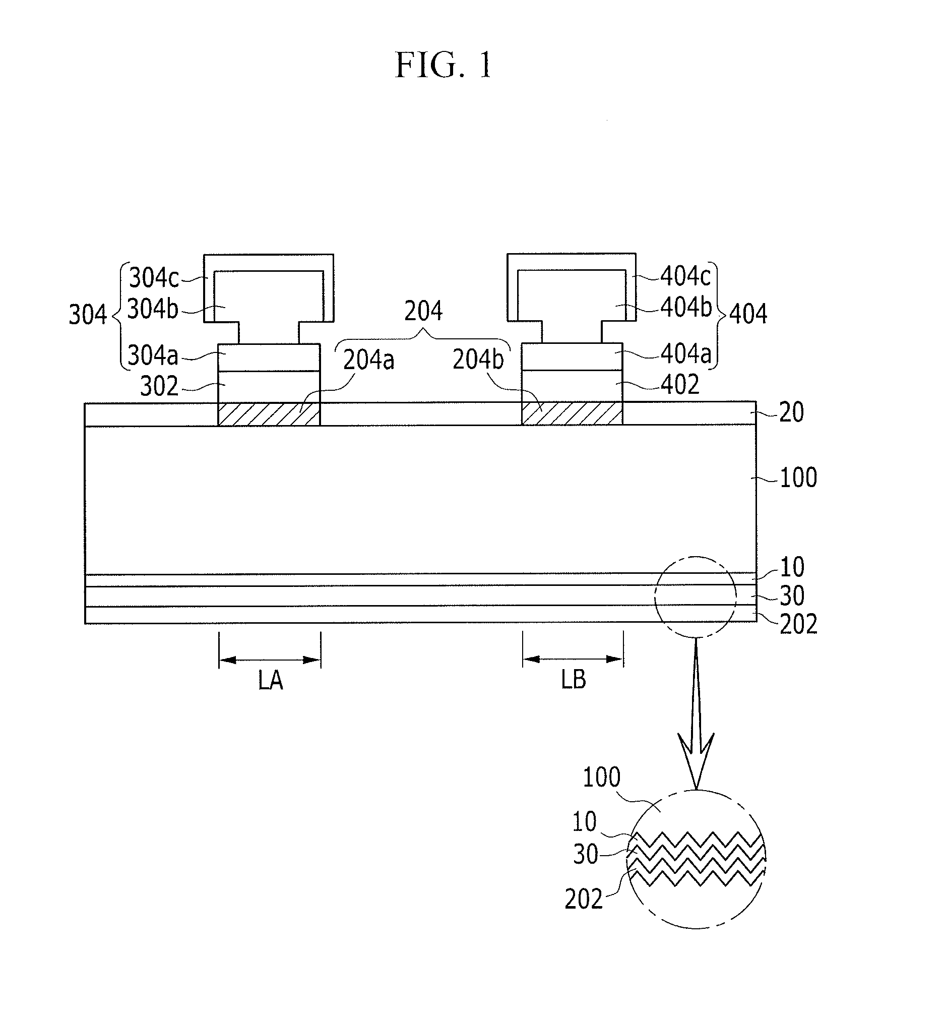
[0029]In the drawing figures, the dimensions of layers and regions may be exaggerated for clarity of illustration. It will also be understood that when a layer or element is referred to as being “on” another layer or substrate, it can be directly on the other layer or substrate, or intervening layers may also be present. Further, it will be understood that when a layer is referred to as being “under” another layer, it can be directly under, and one or more intervening layers may also be present. In addition, it will a...


PUM


Abstract

A solar cell includes a semiconductor substrate, a first intrinsic semiconductor layer and a second intrinsic semiconductor layer on the semiconductor substrate, the first intrinsic semiconductor layer and the second intrinsic semiconductor layer being spaced apart from each other, a first conductive semiconductor layer and a second conductive semiconductor layer respectively disposed on the first intrinsic semiconductor layer and the second intrinsic semiconductor layer, and a first electrode and a second electrode, each including a bottom layer on the first conductive semiconductor layer and the second conductive semiconductor layer, respectively, the bottom layer including a transparent conductive oxide, and an intermediate layer on the bottom layer, the intermediate layer being including copper.

Description

BACKGROUND[0001]1. Field[0002]The described technology relates generally to a solar cell and a manufacturing method. Particularly, the described technology relates generally to a back surface electrode type of solar cell and a manufacturing method thereof.[0003]2. Description of the Related Art[0004]Regarding a solar cell, when an electrode electrically connected to an emitter and a substrate is positioned on a sunlight incidence plane of the solar cell, the electrode is also positioned on the emitter so that a light incidence area may be limited and the efficiency of the solar cell may be reduced.[0005]Therefore, in order to increase the light incidence area, a back contact solar cell has been developed in which electrodes for collecting electrons and holes are positioned on a back surface.[0006]An electrode that is formed by a screen printing method or an electrode that is formed by a plating process is usable for the electrode of the back surface electrode solar cell. The resista...

Claims


Application Information

Patent Timeline
IPC IPC(8): H01L31/0224H01L31/18
CPCH01L31/022441Y02E10/547H01L31/1804H01L31/0747Y02P70/50H01L31/04H01L31/18
Inventor MO, CHAN-BINLEE, DOO-YOULKIM, YOUNG-JINOH, MIN-SEOKLEE, YUN-SEOKSONG, NAM-KYULEE, CHO-YOUNGKIM, YOUNG-SUPARK, YOUNG-SANG
Owner SAMSUNG SDI CO LTD
Why Eureka
Try Eureka