Cooling system for a dry dual clutch of a dual clutch transmission

a dual clutch and cooling system technology, applied in the direction of friction clutches, couplings, clutches, etc., can solve the problems of insufficient cooling, high slip load on the clutch disk, and troublesome clutch odor in the passenger compartment, and achieve the effect of simple technical means

Inactive Publication Date: 2013-05-30
FORD GLOBAL TECH LLC
View PDF7 Cites 2 Cited by
  • Summary
  • Abstract
  • Description
  • Claims
  • Application Information

AI Technical Summary

Benefits of technology

[0009]Continuous intensive cooling is possible and, due to the fact that the fan impeller rotates with the input shaft of the clutch, that is to say preferably with an engine crankshaft, cooling in accordance with the engine speed is automatically possible.
[0010]The fan impeller preferably rotates at the same speed as the shaft coming from the engine, which is synchronized with the input shafts of the dual clutch in accordance with the gear selected. This combination of features can be achieved by particularly simple technical means since the fan impeller need merely be mounted on the engine output shaft or directly coupled thereto.

Problems solved by technology

Dry dual clutches of this kind often may have inadequate cooling and are susceptible to overheating particularly in the case of small engines, where there is a need for frequent gear changes and the clutch disks are subject to high slip loading, especially when starting off or in stop-and-go mode.
In parallel with the overheating, troublesome clutch odor can occur in the passenger compartment when using specific friction linings.
With a cooling system of this kind, the required cooling capacity cannot be provided at high slip speeds.

Method used


Image

  • Cooling system for a dry dual clutch of a dual clutch transmission
  • Cooling system for a dry dual clutch of a dual clutch transmission
  • Cooling system for a dry dual clutch of a dual clutch transmission

Examples


Embodiment Construction

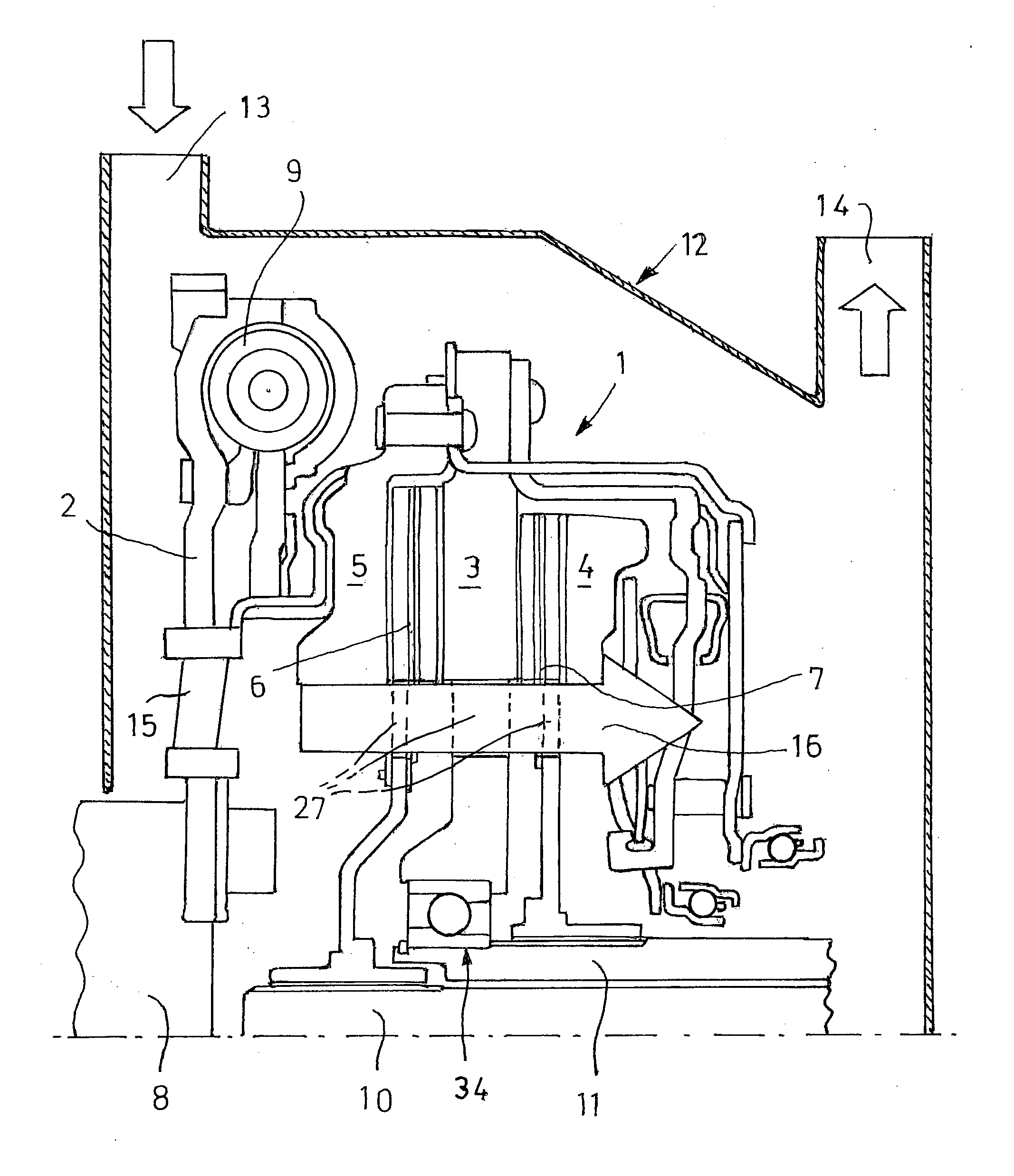
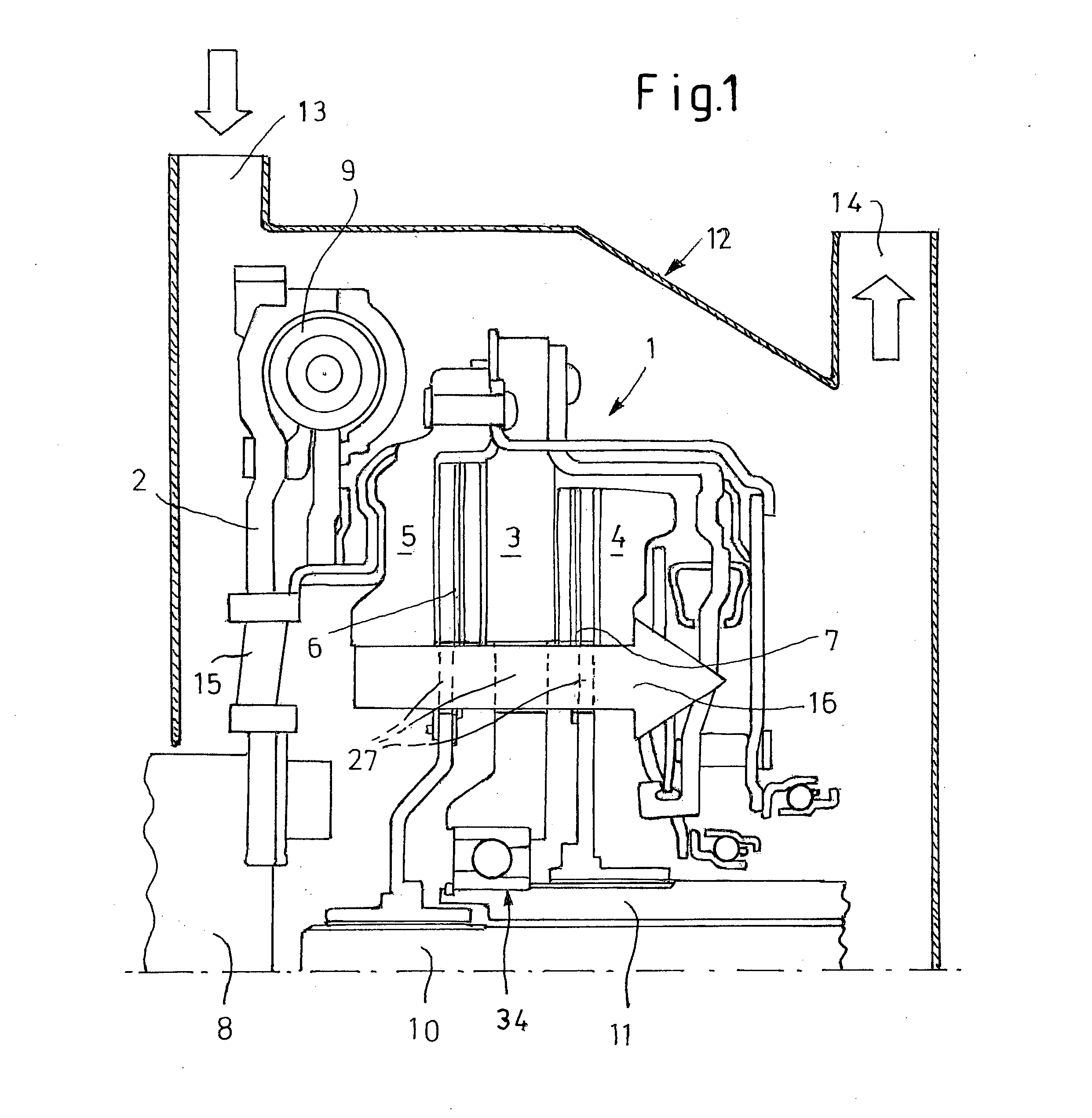
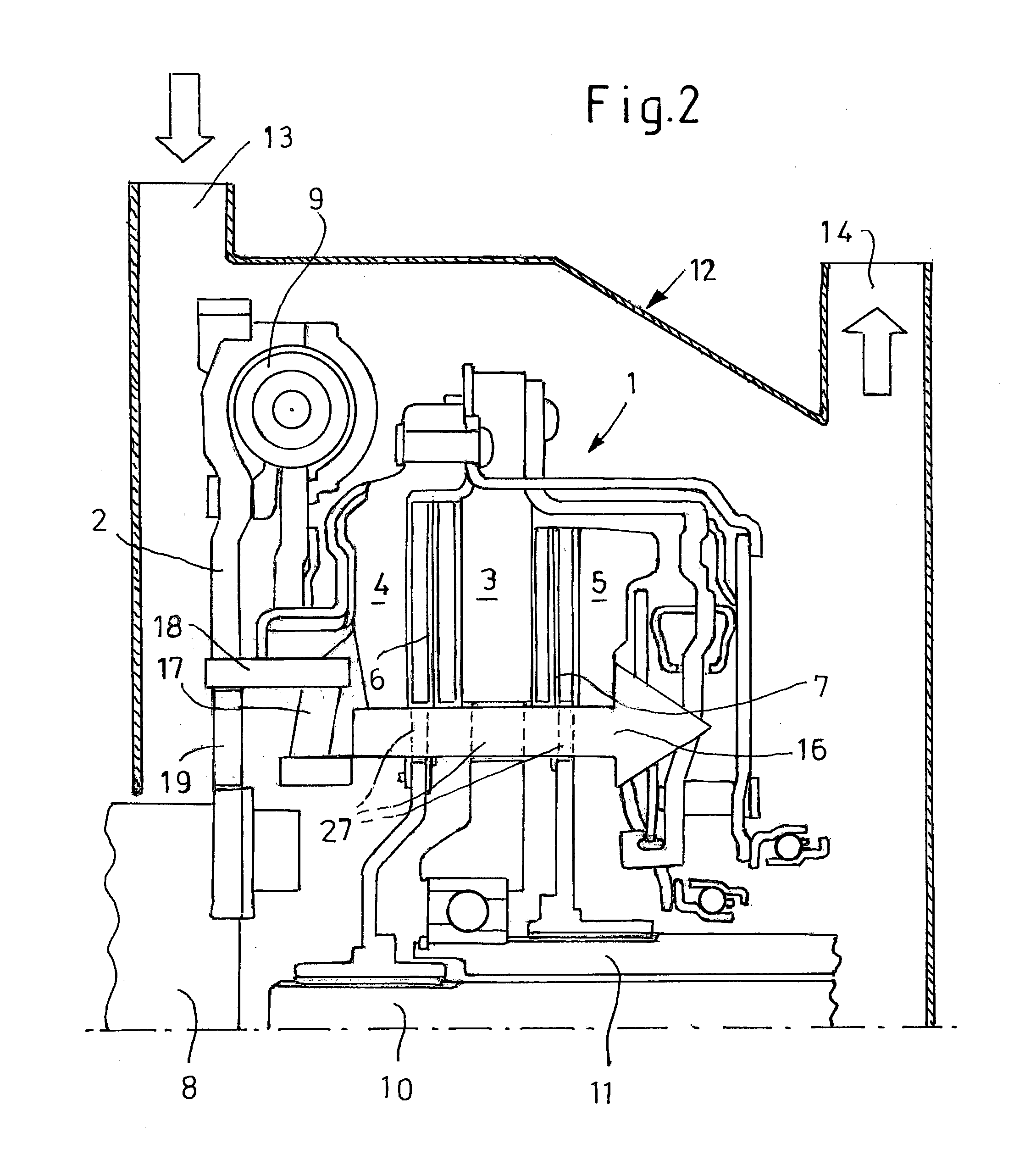
[0026]According to FIG. 1 of the drawing, the dual clutch system 1 essentially consists of a driving disk 2, a central disk 3 connected to the latter, pressure plates 4 and 5 provided on both sides of the central disk 3, and friction disks 6 and 7 located between the central disk 3 and the pressure plates 4 and 5 and supported on hubs secured to output shafts 10 and 11, respectively.

[0027]The driving disk 2 is seated on the input shaft 8 of the dual clutch 1 for conjoint rotation and consequently rotates with the latter at the same speed. The input shaft 8 is normally the drive shaft or crankshaft of an engine (not shown in the drawing).

[0028]The driving disk 2 is connected by way of a torsional damper 9 to the central disk 3, that is to say the central disk 3 revolves at the same speed as the driving disk 2. The pressure plates 4 and 5 arranged on both sides of the central disk 3 revolve with the central disk 3 but can be moved axially relative to the central disk 3. In this arrang...


PUM


Abstract

A dual-clutch for a motor vehicle includes an input, first and second outputs, friction plates for producing a drive connection between the input and the first and second outputs alternately, a housing including an inlet and an outlet, containing at least a portion of the friction plates, and a cooling system including a fan impeller rotating with the input and producing an air stream flowing through the housing from the inlet to the outlet.

Description

BACKGROUND OF THE INVENTION[0001]1. Field of the Invention[0002]The invention relates to a dual-clutch transmission for motor vehicles, having two transmission subsections, a dry dual clutch, which transmits the torque from the engine to one or the other of the two transmission subsections, and a cooling system having a fan impeller for cooling the dual clutch.[0003]2. Description of the Prior Art[0004]Dual clutch transmissions are automatic shift transmissions, which allow a fully automatic gear change without an interruption in power by means of two transmission subsections. The transmission controller chooses the gears automatically or according to driver requirements within the permitted engine speed ranges. Torque is transmitted via one of the two clutches, which connect the two transmission subsections to the engine. While one clutch is closing, the other opens.[0005]Dry dual clutches of this kind often may have inadequate cooling and are susceptible to overheating particularl...

Claims


Application Information

Patent Timeline
Patent Type & Authority Applications(United States)
IPC IPC(8): F16D21/02
CPCF16D21/02F16D13/72F16D2021/0684F16D2021/0615F16D21/06F16D2300/0212
Inventor KIRCHHOFFER, JOHANN
Owner FORD GLOBAL TECH LLC
Why Eureka
Try Eureka