Device for determining the water content of a target

a target and water content technology, applied in the field of target water content determination devices, can solve the problems of affecting the accuracy of measurement optics and other optical elements, affecting the accuracy of measurement, so as to achieve the effect of simple technical means and high measurement accuracy

Active Publication Date: 2013-07-23
CNCMONSTER GMBH
View PDF6 Cites 0 Cited by
  • Summary
  • Abstract
  • Description
  • Claims
  • Application Information

AI Technical Summary

Benefits of technology

[0009]It is thus an object of the invention to provide a device of the above-described kind, which allows water content determination with simple technical means and high accuracy of measurement while requiring minimum service and maintenance.
[0010]Another object of the invention is to conduct the contactless water content determination even if the target has a high water content and under rough measurement conditions without diminishing the accuracy or reliability of the measurement.

Problems solved by technology

Focusing and reflecting the beam, which is required for measurement, involve a relatively high constructive and technical effort.
During operation, device components present in the course of the optical path of the target and reference beams as well as that of the reflected beam are relatively easily contaminated.
In areas of paper manufacturing equipment in which the paper web has a very high water content, the respective environment conditions have not allowed functional measurement so far, as liquid droplets present in the air and other suspended particles result in an immediate blockade of the measurement optics and other optical elements in conventional measurement devices, making operation over an extended period of time impossible.
Again, the relatively high technical effort constitutes a disadvantage here, resulting in an increased failure probability and allowing limited measurement sensibility only.

Method used


Image

  • Device for determining the water content of a target
  • Device for determining the water content of a target
  • Device for determining the water content of a target

Examples


Embodiment Construction

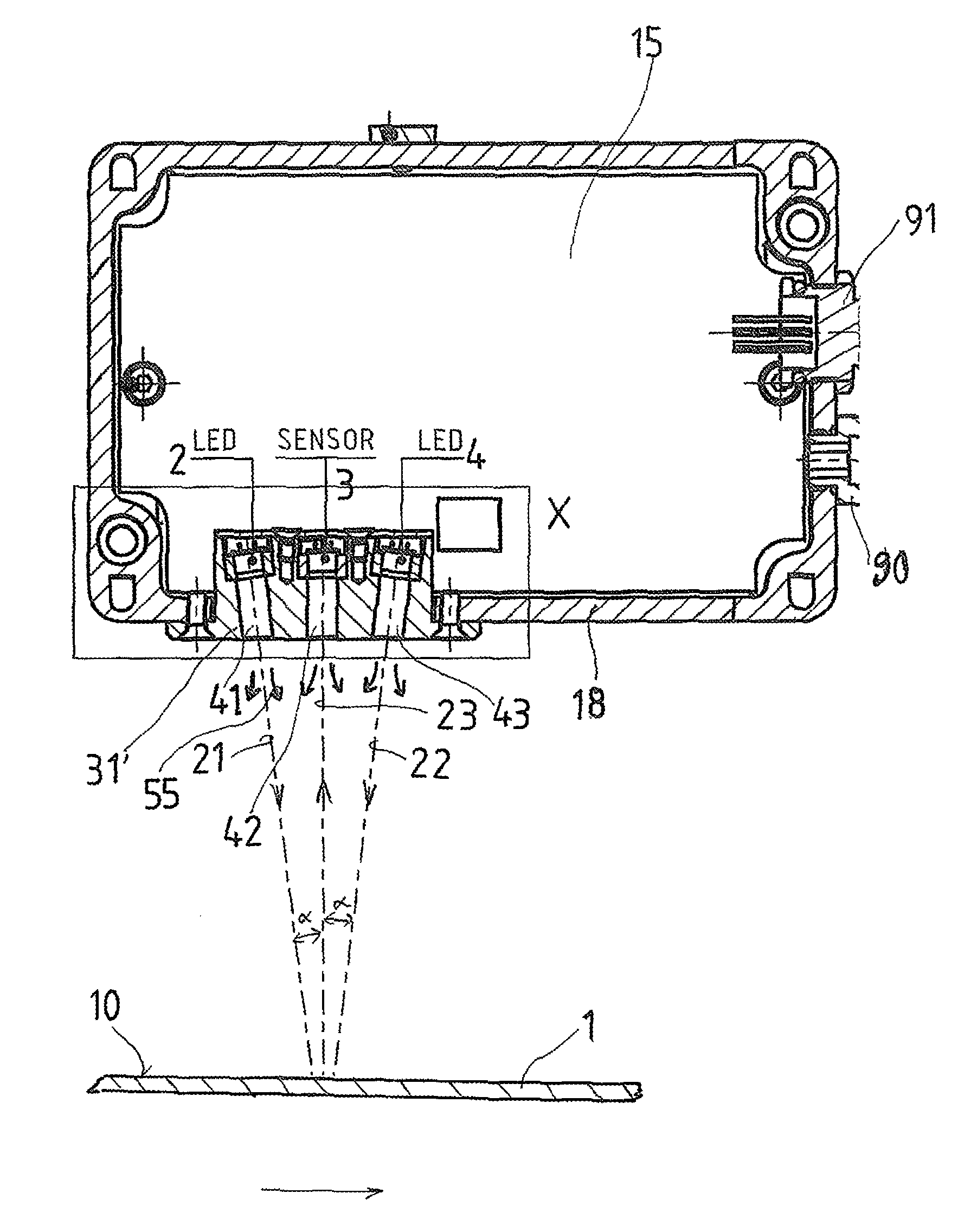
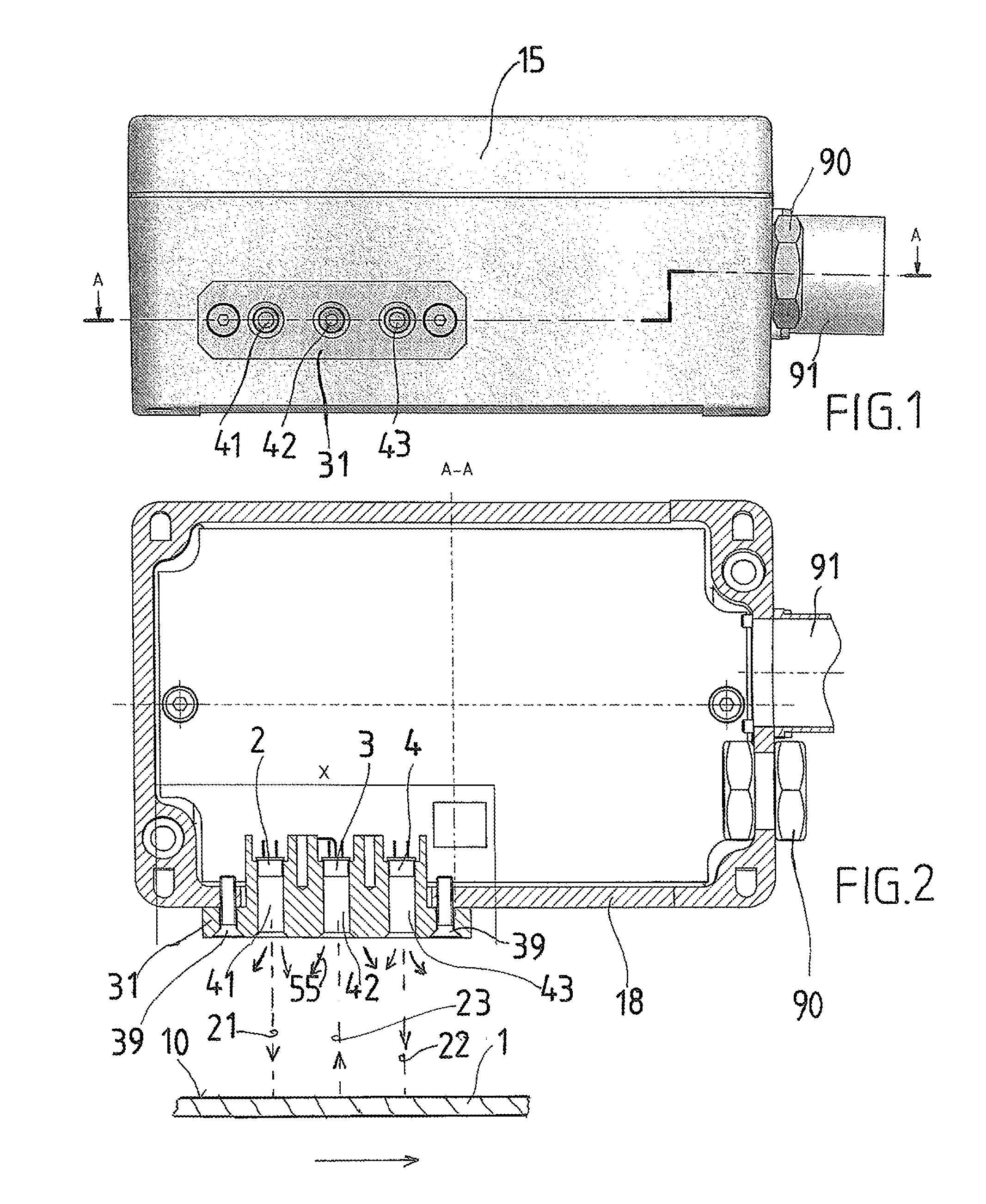
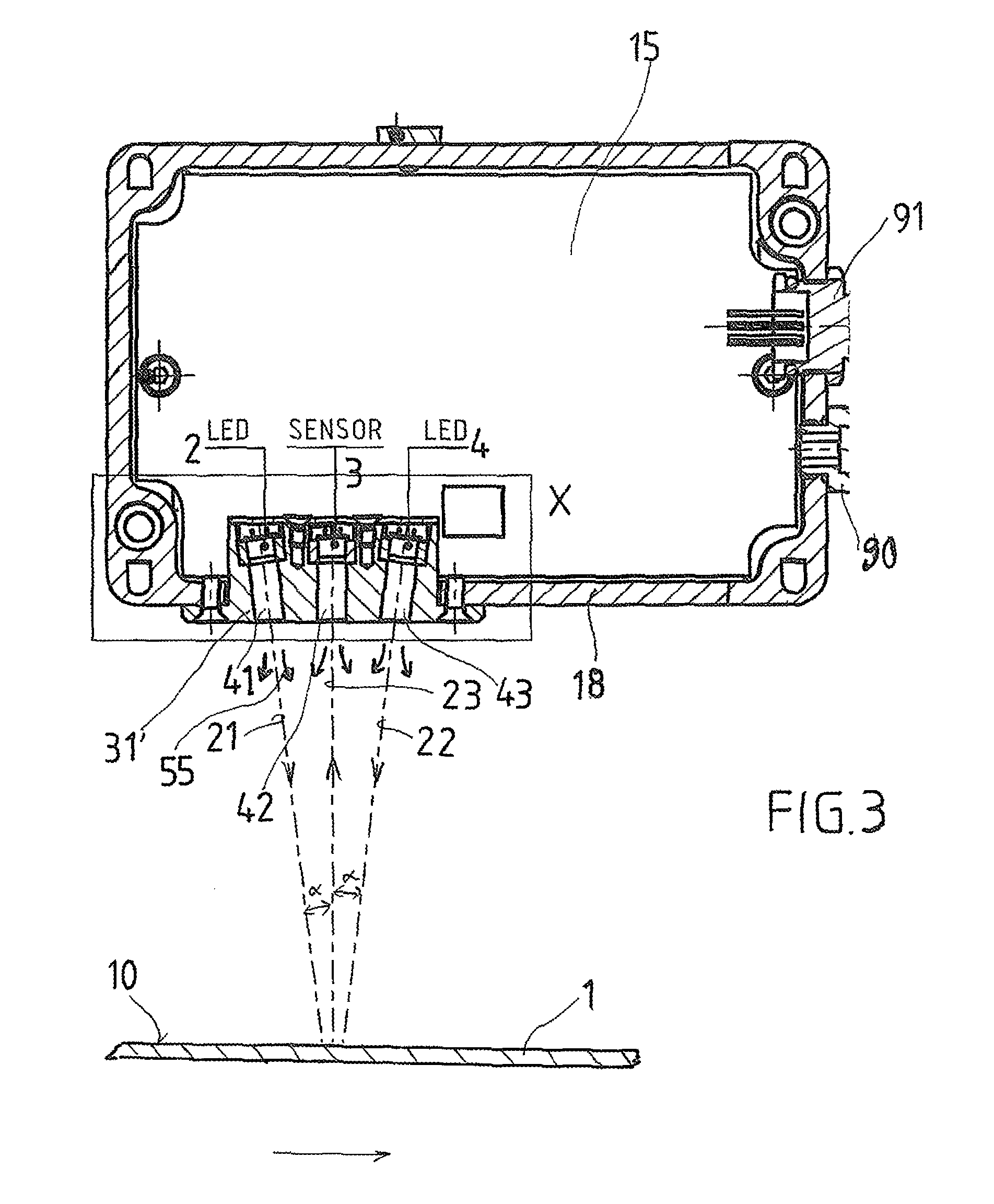
[0065]FIGS. 1 and 2 show a device for determining the water content of a target 1, the device being contained in a two-part box-shaped housing 15. For the sake of simplicity, the signal and control units are not depicted. Electrical energy supply and signal or data transfer to a central unit that is not shown occur via a cable connection 90.

[0066]A holder element 31, which is fixed with screws 39, is embedded in a gas- and pressure-tight way in a breakthrough point of a wall 18 of the bottom half of the housing 15. In the holder element 31, a source of target radiation 2 and a source of reference radiation 4 are held in such a way that they are directed towards a target surface 10 of the target 1. Further, a detecting element 3 is held by the holder element 31 for measuring the intensity of radiation reflected by the target surface.

[0067]According to the invention, the source of target radiation 2, the source of reference radiation 4, and the detecting element 3 are arranged directl...


PUM


Abstract

A device is provided for determining the water content of a target (1), the device having at least one source of target radiation (2), at least one source of reference radiation (4) directed to a target surface (10), and at least one detecting element (3) for measuring the intensity of radiation reflected back by the target surface. During use the at least one source of target radiation (2), the at least one source of reference radiation (4), and the at least one detecting element (3) are arranged immediately opposite the target surface (10). A pressurizing device using air or gas is provided, by which an artificial movement of the air or gas atmosphere can be created in the area of the optical paths between the at least one source of target radiation (2) and the target surface (10), and / or between the at least one source of reference radiation (4) and the target surface (10), and / or between the target surface (10) and the at least one detecting element (3).

Description

CROSS-REFERENCE TO RELATED APPLICATIONS[0001]This application is a Section 371 of International Application No. PCT / AT2010 / 000113, filed Apr. 16, 2010, which was published in the German language on Oct. 21, 2010, under International Publication No. WO 2010 / 118451 A1 and the disclosure of which is incorporated herein by reference.BACKGROUND OF THE INVENTION[0002]The invention relates to a device for determining the water content of a target having at least one source of target radiation and at least one source of reference radiation, both directed to the surface of the target, as well as at least one detecting element for measuring the intensity of the radiation reflected back by the target surface.[0003]Such contactless determination of a water content can be conducted for any target. Such water content determination is particularly but not exclusively required in the manufacture of paper.[0004]In particular, the invention relates to devices for determining the water content of the ...

Claims


Application Information

Patent Timeline
Patent Type & Authority Patents(United States)
IPC IPC(8): D21F7/06
CPCG01N21/15G01N21/3151G01N21/3554G01N21/3559G01N2201/062G01N2201/0623G01N2021/151
Inventor UBLACKER, DIETMAR
Owner CNCMONSTER GMBH
Why Eureka
Try Eureka