
Starter

a technology of starter and internal combustion engine, which is applied in the direction of engine starter, muscle operated starter, rider propulsion, etc., can solve the problems of short circuit and achieve the effect of simple technical means

Inactive Publication Date: 2005-08-30
ROBERT BOSCH GMBH
View PDF7 Cites 6 Cited by
  • Summary
  • Abstract
  • Description
  • Claims
  • Application Information

AI Technical Summary

Benefits of technology

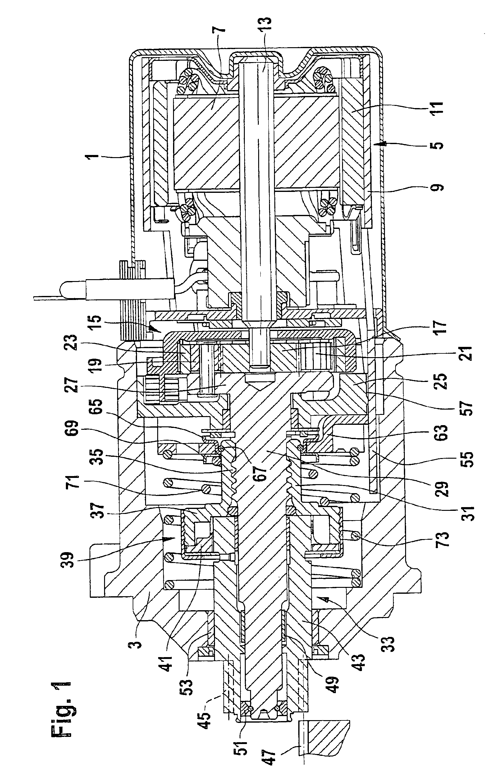
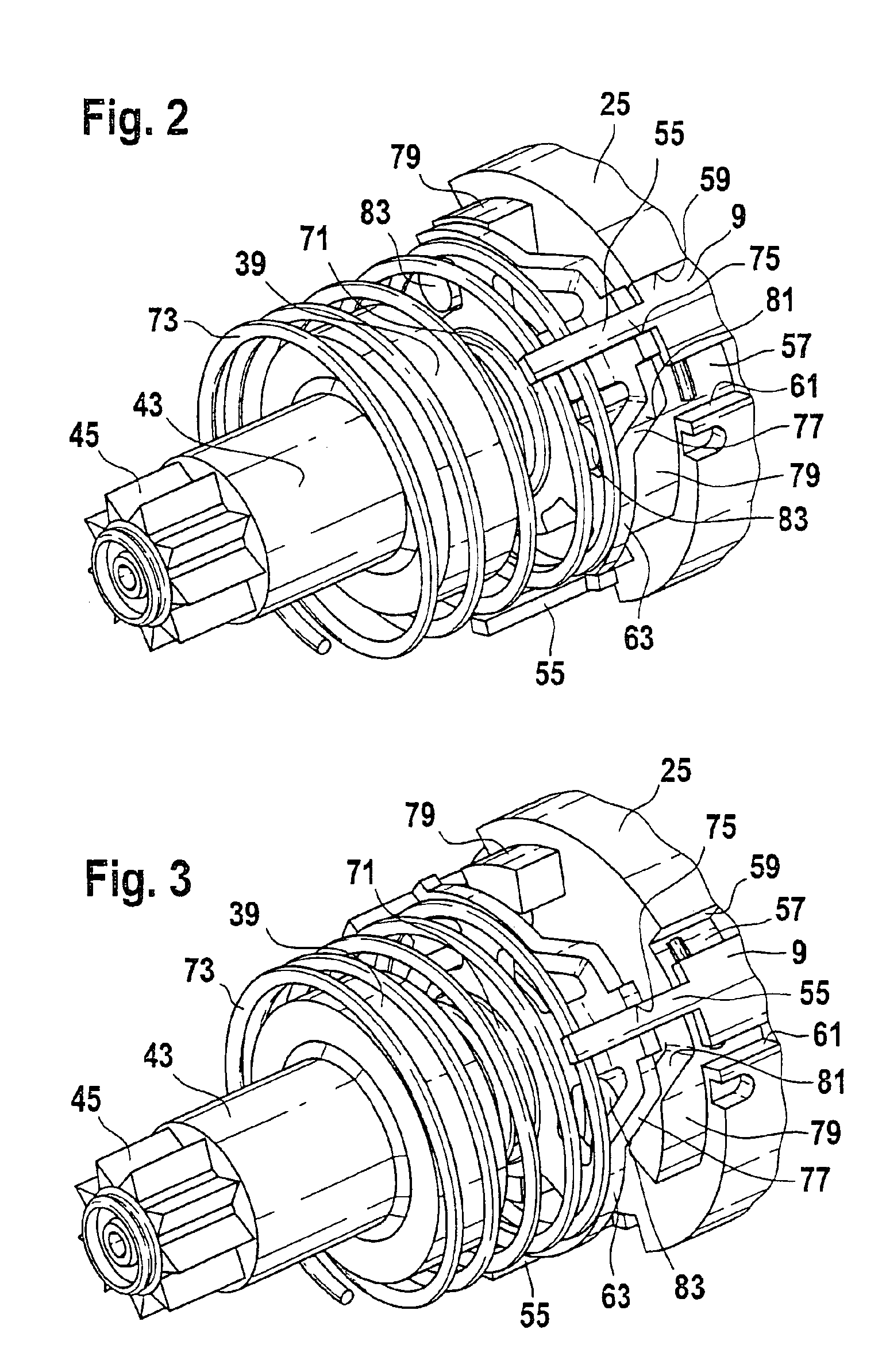
[0004]According to the features of claim 1, means are provided that convert the turning motion of a stator element around the motor axis—which said turning motion is produced when the starter motor is energized—directly into an axial motion acting on the driven shaft. With this invention, a starter relay can be eliminated that initiates a pushing-forward of the driven shaft for the pinion-engaging procedure. Additionally, the conversion of the turning motion of the starter element into an axial motion acting on the driven shaft can be carried out with very simple technical means.
[0013]The invention will be explained in greater detail hereinbelow with reference to exemplary embodiments presented in the drawings.
[0006]An advantageous exemplary embodiment for converting the turning motion of the stator element into an axial motion of the driven shaft can comprise the following: a guide track and a guide device capable of gliding along said guide track are provided, whereby the guide track or the guide device are mechanically linked with the axially displaceable driven shaft, and the guide device or the guide track is located on a part of the starter that does not move axially with the driven shaft. The stator element is mechanically linked with the guide track or the guide device in such a fashion that the guide device glides along the guide track when the stator element executes a turning motion. The guide track and the guide device have shapes that allow the driven shaft to execute an axial motion when the guide device glides along the guide track. Balls or rolling elements, for example, can be inserted to reduce friction between the guide track and the guide device.

Problems solved by technology

Since the starter is located in the crumple zone of a vehicle, there is a danger that, if an accident occurs, parts of the starter relay supplied with battery voltage can come into contact with the grounded vehicle body, which would cause a short circuit.

Method used


Image

  • Starter
  • Starter
  • Starter

Examples


Embodiment Construction

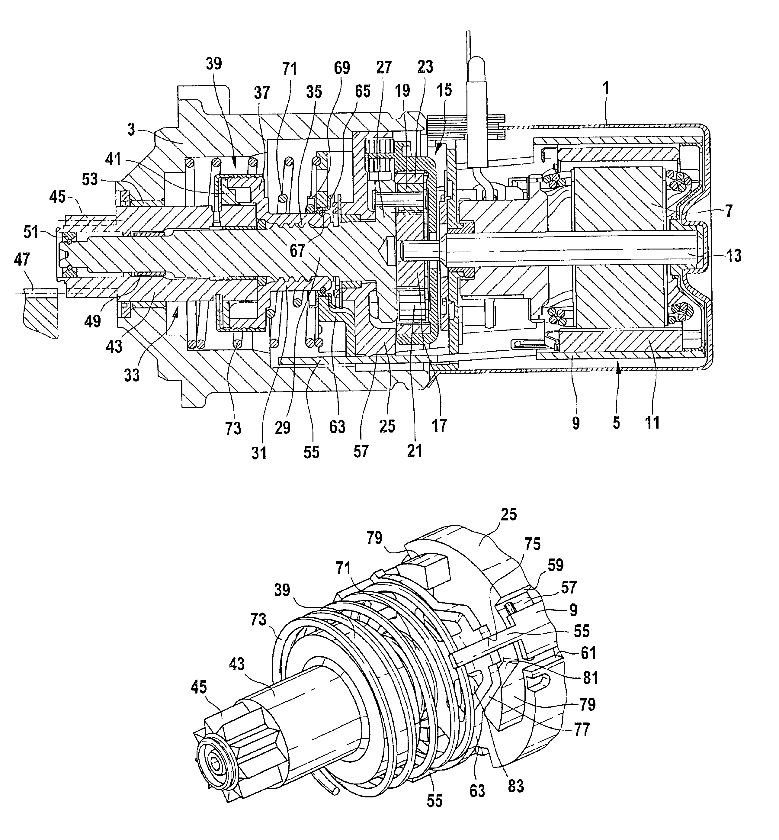
[0017]The starter shown as a longitudinal sectional drawing in the figure comprises a double-component housing, whereby a housing part 1 encloses a starter motor, and a second housing part 3 accommodates the drive end bearing of the starter. The starter motor comprises, in known fashion, a stator 5 and a rotor 7 turnably supported therein. The stator 5 comprises a pole tube 9 and stator poles 11 designed as permanent magnets located therein. The pole tube 9 forms the magnetic yoke for the stator poles 11 that are located concentrically around the rotor 7. The rotor 7 comprises a motor shaft 13 that is interconnected in torsion-resistant fashion with a laminated stack. One or more rotor windings are inserted in not-shown grooves of the laminated stack.

[0018]The motor shaft 13 projecting out of the starter motor is coupled with a gearset, preferably a planetary gearset 15. The motor shaft 13 drives a sun gear 17, and the sun gear 17 meshes with planet gears 19 and 21 that walk around ...


PUM


Abstract

An inertia-drive starter is proposed, in the case of which a relay is not required to engage the pinion in the flywheel ring gear (47) of an internal combustion engine. With this starter, a pushing-forward of the driven shaft (33) to engage a pinion (45) in the flywheel ring gear (47) is brought about by means of a pole tube (9) located on the stator (5) of the starter motor (5, 7), which said pole tube executes a turning motion around the motor axis when the starter motor (5, 7) is energized. Means (55, 63, 77, 79) are provided that convert the turning motion of the pole tube (9) directly into an axial motion acting on the driven shaft (33).

Description

BACKGROUND OF THE INVENTION[0001]The present invention concerns a starter for an internal combustion engine that comprises a starter motor, a drive shaft capable of being driven by the starter motor, and a driven shaft that is mechanically linked with the drive shaft and is displaceable in the direction of its longitudinal axis, which said driven shaft is equipped with a pinion capable of being pushed into mesh with a flywheel ring gear of the internal combustion engine, whereby a pushing-forward of the driven shaft to engage the pinion in the flywheel ring gear takes place by means of an element located on the stator of the starter motor that executes a turning motion around the motor axis when the starter motor is energized.[0002]“Inertia-drive” starters are widespread as starters for internal combustion engines. These inertia-drive starters have an electrical starter motor, the drive shaft of which is mechanically linked with a driven shaft that is displaceable in the direction o...

Claims


Application Information

Patent Timeline
Patent Type & Authority Patents(United States)
IPC IPC(8): F02N15/06F02N15/02F02N11/00H02K7/06H02K7/10H02K7/12
CPCF02N15/066F02N15/067Y10T74/131Y10T74/134Y10T74/139F02N11/00
Inventor SIEMS, HANS-DIETERRICHTER, INGOHARTMANN, SVENBRAUN, HANSKUGLER, JUERGEN
Owner ROBERT BOSCH GMBH
Learn More