Automotive Camera System and Its Calibration Method and Calibration Program

Inactive Publication Date: 2013-05-30
CLARION CO LTD
View PDF5 Cites 47 Cited by
  • Summary
  • Abstract
  • Description
  • Claims
  • Application Information

AI Technical Summary

Benefits of technology

[0011]According to the present invention, the intrinsic parameter and the extrinsic parameter of the image taking unit can be easily calibrat

Problems solved by technology

This method however can correct only the optic axis of the automotive camera and the information on the road sign, and cannot correct intrinsic

Method used


Image

  • Automotive Camera System and Its Calibration Method and Calibration Program
  • Automotive Camera System and Its Calibration Method and Calibration Program
  • Automotive Camera System and Its Calibration Method and Calibration Program

Examples


Embodiment Construction

[0022]Hereinafter, an embodiment of the present invention is described in detail with reference to the drawings.

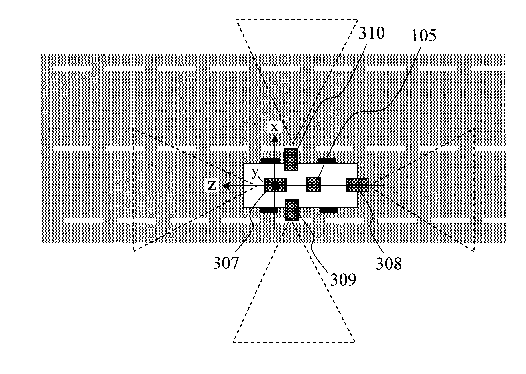
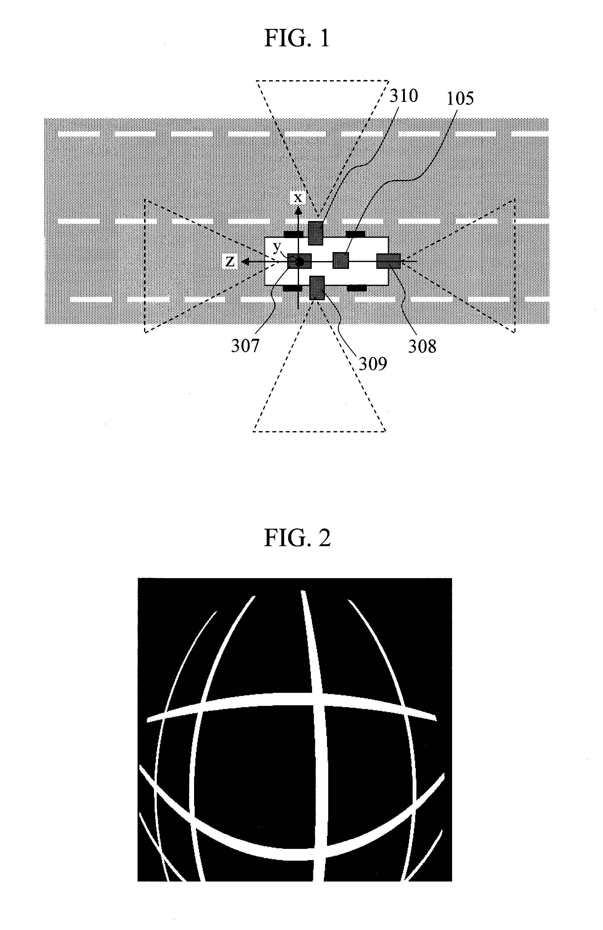
[0023]FIG. 1 is a model diagram illustrating the state where a vehicle on which an automotive camera system according to the present embodiment is mounted is running on a road.

[0024]For example, as illustrated in FIG. 1, the automotive camera system includes image taking units 307, 308, 309, and 310 and an image processing device 105. The image taking units 307, 308, 309, and 310 and the image processing device 105 have been put into practical use for the purpose of monitoring for improvement in convenience of the vehicle and driving safety on the basis of image information from road markers, road signs, and the like, and can be applied to the embodiment of the present invention.

[0025]In the present embodiment, four cameras that each monitor an area around the vehicle are attached as the image taking units 307, 308, 309, and 310, but any number (equal to or more than one) ...


PUM


Abstract

Provided is a calibration method for an automotive camera system that can easily calibrate intrinsic parameters and extrinsic parameters of an image taking unit. A calibration method for an automotive camera system 1 includes: recognizing a recognition target object including a preset straight line portion, from an image taken by each of image taking units 307 to 310, and extracting feature points of the recognition target object from the image; projecting the feature points onto a virtual spherical surface 601, estimating intrinsic parameters of the image taking units 307 to 310 on the basis of a shape of a feature point sequence formed on the virtual spherical surface 601, and calibrating the estimated intrinsic parameters; and calculating an overhead point of view of the image on the basis of the feature points, estimating extrinsic parameters of the image taking units 307 to 310 on the basis of the calculated overhead point of view, and calibrating the estimated extrinsic parameters.

Description

BACKGROUND OF THE INVENTION[0001]1. Field of the Invention[0002]The present invention relates to an automotive camera system that recognizes an image of an environment around a vehicle, as well as its calibration method and calibration program.[0003]2. Background Art[0004]An automotive camera system including an image taking unit and an image processing device has objects to improve the convenience of a vehicle, achieve driving safety, and perform advanced position correction of a car navigation, and the role of the automotive camera system is becoming increasingly important. Along with development in image processing technology, a wide variety of techniques have been developed for recognizing a road surface or indications and objects on a road. Consequently, techniques for recognizing an image of an environment around a vehicle to perform vehicle control for lane departure prevention, collision avoidance, autocruise, and the like have also been developed and started to be put into ...

Claims


Application Information

Patent Timeline
IPC IPC(8): G06K9/00
CPCG06T7/0018G06K9/00791G06T7/80G06V20/56
Inventor SAKANO, MORIHIKOSATO, KEIJISHIMA, TAKESHI
Owner CLARION CO LTD
Why Eureka
Try Eureka