Disk drive device

Inactive Publication Date: 2013-05-30
HITACHI CONSUMER ELECTRONICS CORP +1
View PDF3 Cites 3 Cited by
  • Summary
  • Abstract
  • Description
  • Claims
  • Application Information

AI Technical Summary

Benefits of technology

The present invention is about a disk drive device that can prevent warping deformation in the center part of the disk tray and restrain resonance phenomenon that causes warping deformation while producing vibration displacement of the center part in the width direction of the disk tray in both upward and downward directions. This can prevent recording / reproduction errors and increased noise due to rattle vibration.

Problems solved by technology

The amplitude of the vertical vibration in the width direction in the central part of the disk tray in the warping deformation mode caused by the resonance phenomenon, is large, causing the recording / reproduction error by excitation of the pick up that records information on the disk and reproduces the information on the disk, and causing, problem including increased noise due to rattle vibration.
However, in the conventional disk drive devices, there has been no sufficient consideration on the vertical vibration in the center part in the width direction of the disk tray in the warping deformation mode due to the resonance phenomenon.
Consequently, it has not been possible to restrain resonance phenomenon in the center part in the width direction of the disk tray causing warping deformation of the center part in the width direction of the disk tray while producing vibration displacement in the vertical directions, not only in the downward direction, but also the upward direction.
However, when a resonance phenomenon is caused in which the center part in the width direction of the disk tray produces vibration displacement in the upward and downward directions while causing warping deformation, even if it is possible to restrain the warping deformation of the center part in the width direction of the disk tray to the upper side by the flexure elasticity of the flange, it is not possible to restrain the resonance phenomenon by the warping deformation in the center part in the width direction of the disk tray to the lower side, since flexure elasticity of the flange is released to enhance the warping deformation of the center part in the width direction of the disk tray to the lower side.

Method used


Image

  • Disk drive device
  • Disk drive device
  • Disk drive device

Examples


first embodiment

[0054]FIG. 4 is a schematic diagram of the warping deformation restraining mechanism of the first embodiment, which is a general cross-section of the optical disk drive device viewed in the direction indicated by arrows B-B in FIG. 1. FIG. 4A shows a state where the disk tray is ejected to the outside from the opening of the casing, FIG. 4B shows a state where the disk tray is introduced to the predetermined introduction position within the casing, and retained in a predetermined introduction position by a locking mechanism that is not shown, by resisting to urging force of the disk tray extruder mechanism, and FIG. 4C-4D show magnification of an inner part abutment part of the warping deformation restraining mechanism according to the present embodiment.

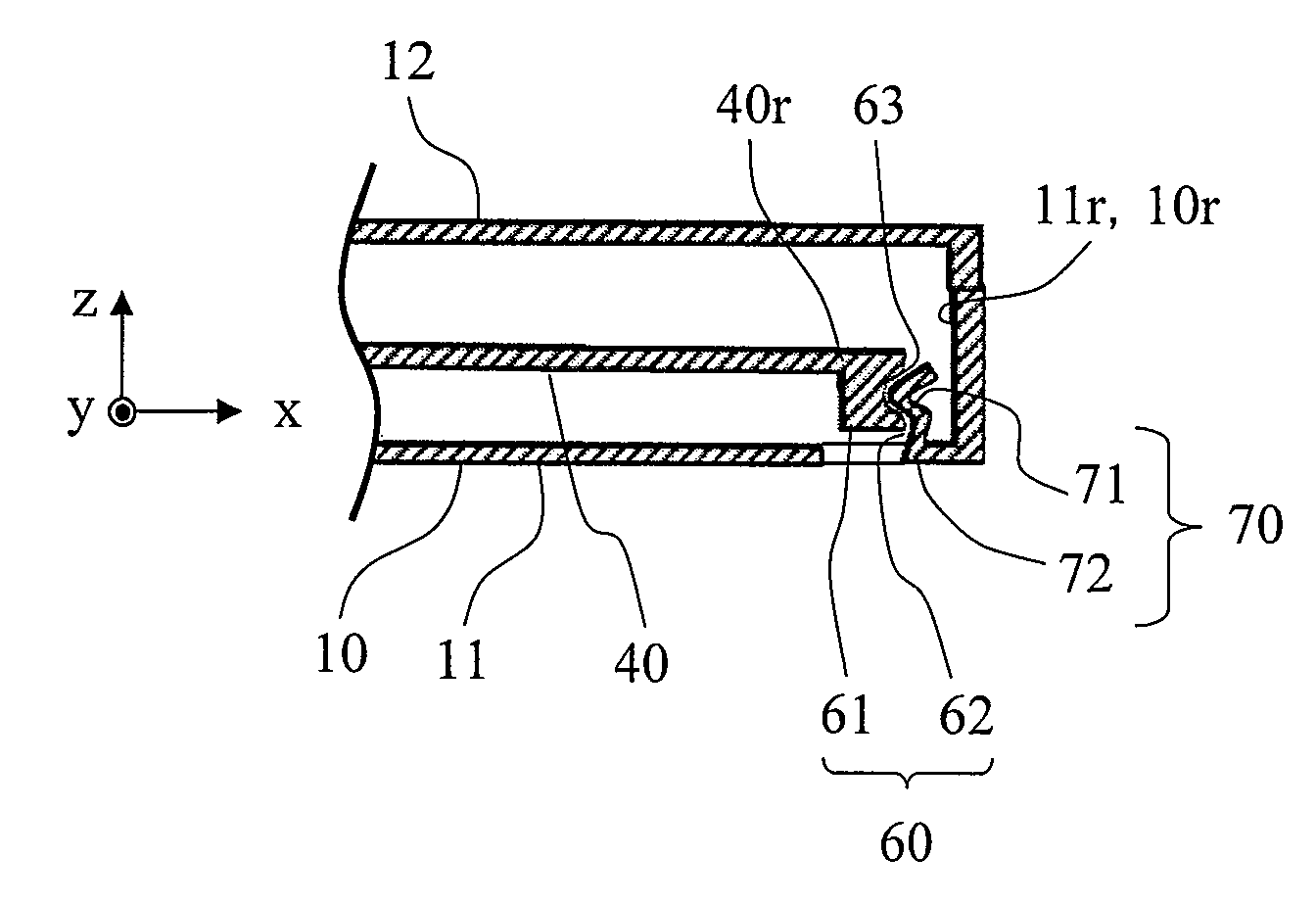
[0055]The warping deformation restraining mechanism 60 is configured to comprise an introduction side abutment part 61 provided in the disk tray 40 side and an inner part abutment part 62 provided in the casing 10 side. The introduc...

second embodiment

[0076]FIG. 5 is a schematic diagram of the warping deformation restraining mechanism, and a general cross-section of the optical disk drive device in which the back side part in the front and back directions (x direction) of the optical disk drive device is viewed in the direction indicated by arrows B-B in FIG. 1. FIG. 5A shows a state in which the disk tray 40 is ejected to the outside from the opening 13 of casing 10, and FIG. 5B shows a state in which the disk tray 40 is introduced to a predetermined introduction position within the casing 10.

[0077]In the warping deformation restraining mechanism 60 of the present embodiment, a protruding portion 64 is formed on the abutment surface of the introduction side abutment part 61, instead of forming the groove section 63 or the concave portion as in the first embodiment shown in FIG. 4. The elastic member 65 of the inner part abutment part 62, by being pressed by the abutment on the protruding portion 64 of the introduction side abutm...

third embodiment

[0081]FIG. 6 is a schematic diagram of the warping deformation restraining mechanism, which is a general cross-section in which the back side part in the front and back directions of the optical disk drive device (x direction) is viewed from the direction indicated by arrows B-B in FIG. 1. FIG. 6A shows a state in which the disk tray 40 is ejected to the outside from the opening 13 of the casing 10, and FIG. 6B shows a state in which the disk tray 40 is introduced to a predetermined introduction position within the casing 10.

[0082]In the warping deformation restraining mechanism 60 of the present embodiment, the elastic member 65 of the inner part abutment part 62 is formed by a plate spring member 70 instead of the elastic material having an elastic deformation property, and also a vibration dumping (vibration-proof) property, as in the first embodiment shown in FIG. 4.

[0083]The plate spring member 70 is, as shown in FIG. 6, formed so that bent tip part 71 having cross-sectional sh...


PUM


Abstract

A disk drive device that can prevent warping deformation in upward and downward directions of a disk tray and can prevent vibration in a warping deformation mode without producing a rattle vibration is provided. A disk drive device has a casing and a disk tray on which the spindle motor and the pickup are mounted; and a pair of parallel first and second guide mechanisms that slidably supports the disk tray so as to eject the disk tray from the casing to the outside. In the disk drive device, in a center part in a width direction along the disk mount surface of an introduction side distal end part of the disk tray, an introduction side abutment part having a groove section or a protruding portion is formed, and an inner part abutment part formed on an elastic member is installed on an inner side inner wall part.

Description

BACKGROUND OF THE INVENTION[0001]1. Field of the Invention[0002]The present invention relates to a disk drive device that performs recording and reproduction of information. Specifically, the present invention relates to a tray-type disk drive device that has a disk mounted on a disk tray ejected from the casing of the device and introduces the disk together with the disk tray into the casing of the device.[0003]2. Background Art[0004]As a tray-type disk drive device, JP Patent Publication (Kokai) No. 2002-279717A (2002) discloses a configuration in which a lib-shaped abutment part is formed to project to the lower side in a height direction (thickness direction (upward and downward directions)), positioned in a center part of the width direction (left and right directions) on a back face with respect to the disk mount surface (front surface) of the disk tray, on the introduction side (back side of the front and back sides) of the introduction / ejection directions (front and back dir...

Claims


Application Information

Patent Timeline
IPC IPC(8): G11B17/056
CPCG11B17/056
Inventor YAMASAKI, TATSUYANISHIDA, IKUONAGAMINE, HIDEYUKIMATSUMOTO, KOJIASANO, SHINYAYAMAUCHI, YOSHIAKIKINOSHITA, YASUSHI
Owner HITACHI CONSUMER ELECTRONICS CORP
Why Eureka
Try Eureka