Brake hydraulic pressure control device

A control device and brake hydraulic technology, applied in the direction of brakes, brake types, bicycle brakes, etc., to achieve the effect of improving disassembly and suppressing resonance phenomenon

Active Publication Date: 2021-01-08
ROBERT BOSCH GMBH
View PDF8 Cites 0 Cited by
  • Summary
  • Abstract
  • Description
  • Claims
  • Application Information

AI Technical Summary

Problems solved by technology

[0007]Furthermore, if a hydraulic unit fails after the hydraulic unit is installed on the vehicle body, the hydraulic unit may be removed for inspection or the like.

Method used


Image

  • Brake hydraulic pressure control device
  • Brake hydraulic pressure control device
  • Brake hydraulic pressure control device

Examples


Embodiment Construction

[0023] Preferred embodiments of the present invention will be described in detail below with reference to the drawings. In addition, in this specification and drawings, the same code|symbol is attached|subjected about the structural element which has substantially the same functional structure, and repeated description is abbreviate|omitted.

[0024]

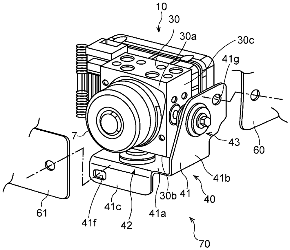
[0025] figure 1 An example of the brake hydraulic circuit 100 to which the brake hydraulic pressure control device 70 according to the embodiment of the present invention can be applied is shown.

[0026] figure 1 The illustrated brake hydraulic circuit 100 is mounted on, for example, a two-wheeled motorcycle, and is configured as a known hydraulic circuit for antilock brake control. Here, the anti-lock brake control (so-called ABS control) refers to control that suppresses the locked state of the wheels by intermittently reducing the brake fluid pressure during vehicle braking, for example. In addition, in the following, f...


PUM


Abstract

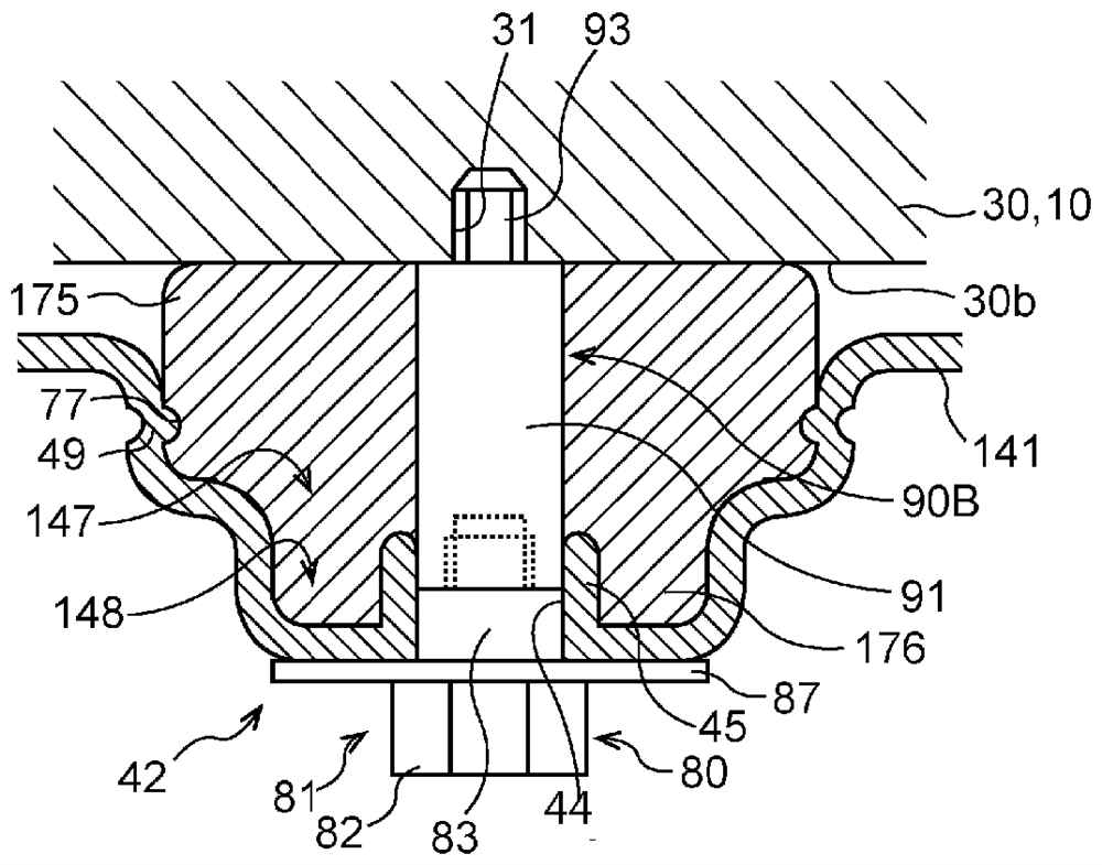
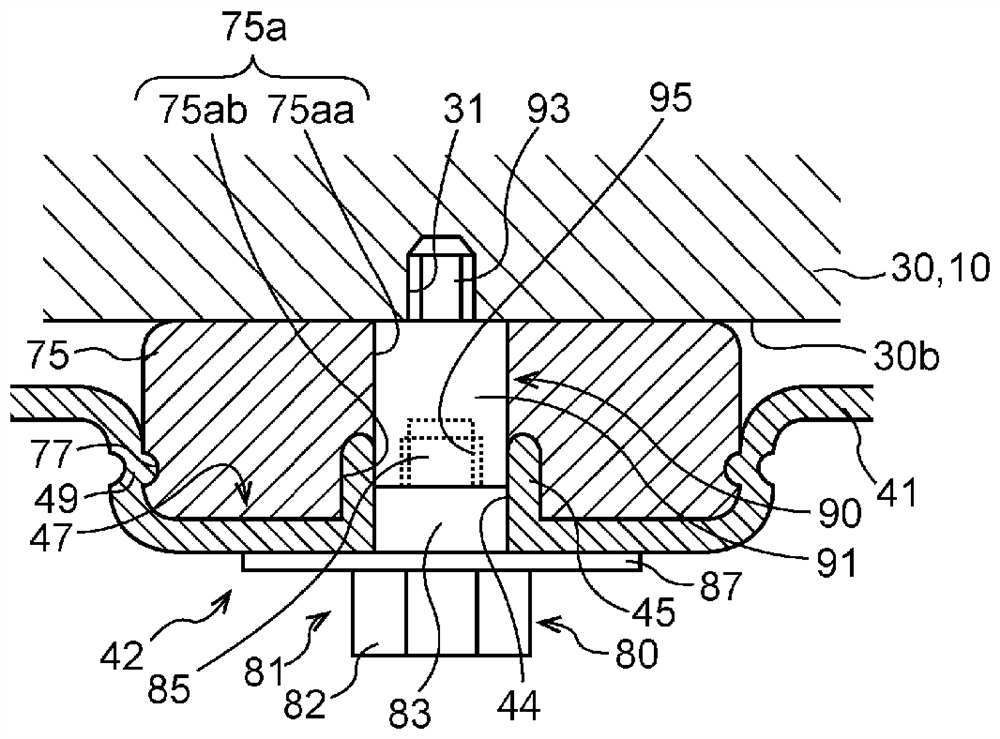
A support part (42, 43) with which it is possible to suppress the occurrence of resonance phenomena in a hydraulic pressure unit and improve the detachability of the hydraulic pressure unit from a bracket is provided with: a fixing member (80) affixed to a housing (30) of the hydraulic pressure unit (10); and a vibration absorbing member (75) which is interposed between the housing (30) and the bracket (41) and has a through hole (75a) through which the fixing member (80) penetrates. The vibration absorbing member (75) includes two vibration absorbing members (75B, 75C, 75D) having different degrees of impact resilience, and, in a state in which a portion of the vibration absorbing member (75) is contained in a recessed section (47) of the bracket (41), is held between the housing (30) andthe bracket (41).

Description

technical field [0001] The invention relates to a brake hydraulic pressure control device. Background technique [0002] Conventionally, there is known a brake hydraulic pressure control device in which a hydraulic unit is attached to a vehicle body via a bracket, and the hydraulic unit controls the hydraulic pressure of brake fluid supplied to a brake portion using a hydraulic circuit to perform brake control. In the brake hydraulic pressure control device, the hydraulic unit is supported by a bracket via a support portion having a single vibration-proof member assembled in an opening formed in the bracket (for example, refer to Patent Document 1). [0003] Patent Document 1: Japanese Patent Laid-Open No. 2015-113899. [0004] When vibration of a frequency close to the natural frequency of the vibration system of the hydraulic unit is applied from the vehicle side, a resonance phenomenon occurs and the hydraulic unit vibrates greatly. In the conventional support structure...

Claims


Application Information

Patent Timeline
Patent Type & Authority Applications(China)
IPC IPC(8): B60T8/36F16F3/093
CPCB60T8/3685F16F3/093B60T2270/10B62L3/023F16D65/0056F16D65/18F16D2121/02
Inventor 坂本贵纪
Owner ROBERT BOSCH GMBH
Why Eureka
Try Eureka