Motor driving system and method

A drive system and motor technology, applied in electric components, controlling multiple AC motors, electrical components, etc., can solve problems such as lack of reliability

Inactive Publication Date: 2012-11-28
HITACHI LTD
View PDF9 Cites 0 Cited by
  • Summary
  • Abstract
  • Description
  • Claims
  • Application Information

AI Technical Summary

Problems solved by technology

[0009] In the above-mentioned invention, there is a problem that shaft torsional vibration occurs on the generator shaft, and the vibration is transmitted to the motor drive inverter as a change in the terminal voltage of the generator, causing a change in the terminal voltage of the motor and vibrating the motor shaft. The vibration further vibrates the shaft of the generator, thus generating a resonance phenomenon. Such a resonance phenomenon must be controlled by changing the control angle or eliminating the vibration component of the power generating device to suppress the vibration. When performing the control In terms of the accuracy of the system, the reliability of the suppression effect of the resonance phenomenon is relatively lacking in the case of malfunctions or failures of the control devices involved in the system.

Method used


Image

  • Motor driving system and method
  • Motor driving system and method
  • Motor driving system and method

Examples


Embodiment approach 1

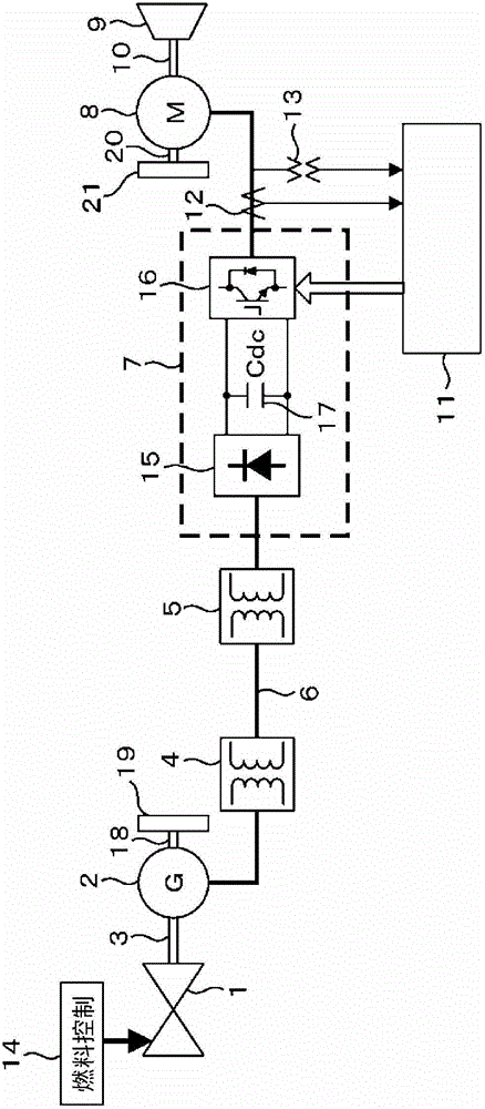
[0058] figure 1 It is an overall structure diagram of the present invention. A gas turbine 1 and a generator 2 converting the mechanical energy of said gas turbine 1 into electrical energy are combined via a generator shaft 3 . The inertial rotator 19 is an inertial rotator 19 for changing the axial torsional resonance frequency of the generator shaft 3 by rotating integrally with the generator 2 , and is passed through a generator shaft with a higher rigidity than the generator shaft 3 . 18 is combined with generator 2. The fuel control device 14 controls the rotational force and speed of the gas turbine 1, the transformer 4 converts the output voltage of the generator 2 to the system voltage, the transformer 5 converts the system voltage into the input voltage of the power converter, and the transformer 4 and Transformer 5 is connected via system 6 . The power converter 7 converts the power output from the transformer 5 into desired power, and includes: a converter 15 com...

Embodiment approach 2

[0116] In Embodiment 1, one generator and one motor are respectively connected. However, in this embodiment corresponding to a larger-scale power plant, if Figure 7 As shown, there are i generators 2 and j motors 8, and they are connected to a common system. But when Figure 7 , the description of the symbols is the same as figure 1 The situation is the same. In this case, when the shaft resonance frequency of generator i is fn(i) and the shaft resonance frequency of motor j is fr(j), by making h(i, j)=fr(j) / fn(i ) all combinations of the resonance ratio h(i, j) defined satisfy h(i, j) ≤ 0.9 or h(i, j) ≥ 1.1, so no matter what the operating state is, the calculation part of the electrical system damping coefficient 30 is D e are all above 1, thus ensuring the stability of the system. As an example, consider a system in which three generators and three motors are connected to a common system. Specifically, the resonance frequency of each generator shaft is fn(1)=10[Hz],...

Embodiment approach 3

[0118] In carrying out the first and second embodiments described above, a mechanism for accurately estimating the resonance frequencies fn and fr of the generator shaft and the motor shaft is required. Therefore, in the present embodiment, a wide-band excitation torque applying mechanism such as an M-series signal or white noise is provided to the motor 8 and the generator 2 . exist Figure 8 Among them, a changeover switch 100 or 101 is provided, which is a switch for switching the application object of the vibration excitation torque to a generator or a motor. When the B side contact is selected, the structure that applies vibration torque to the motor side. In addition, the changeover switches 100 and 101 may also be a physically linked structure. On the other hand, the power converter control device 11 is composed of the following devices: a current controller 102 including a PWM output; a current deviation calculator 104; a signal generation source 103 for M series sig...


PUM


Abstract

The present invention provides a motor driving system capable of suppressing vibration of a resonance phenomenon independent of special control. The resonance phenomenon is characterized in that: shaft twisting vibration occurs on a generator shaft, the vibration becomes generator terminal voltage variation to be transmitted towards an inverter for driving the motor, so that the generator terminal voltage varies and the motor shaft vibrates, and the vibration further enables the generator shaft to vibrate. The motor driving system has a prime motor, a generator for generating electricity through driving of the prime motor, a converter for converting the electric power generated by the generator into the electric power with an expected frequency, a motor driven through the electric power supplied from the converter, and a driven device driven by the motor; wherein, a shaft resonant frequency of the generator shaft for transmitting a driving force of the prime motor towards the generator is different from a shaft resonant frequency of the motor shaft for transmitting a driving force of the motor towards the driven device.

Description

technical field [0001] The present invention relates to a motor drive system and method most suitable for preventing resonance phenomenon caused by shaft torsional vibration of a generator shaft connecting a prime mover and a generator, and a motor shaft connecting a motor and a driven device. Background technique [0002] In recent years, from the viewpoint of energy saving, a technology in which a power converter converts electric power generated by a generator into a variable frequency to drive rotating loads such as compressors, fans, and blowers with electric motors has been widely used. For example, up to now, a system directly driven by a steam turbine or a gas turbine has been electrified with a variable speed drive through an electric motor and a power conversion device. Depending on the system, there is a steam turbine generator as a power supply device, and the electric energy obtained by it is The case of variable speed drive by converting the power conversion de...

Claims


Application Information

Patent Timeline
Patent Type & Authority Applications(China)
IPC IPC(8): H02P5/74H02K7/02
CPCY02E60/16
Inventor 名仓宽和永田浩一郎伊藤雄太秋田佳稔
Owner HITACHI LTD
Why Eureka
Try Eureka