
Tunable humidity sensor with integrated heater

Active Publication Date: 2013-06-06
STMICROELECTRONICS SRL +1
View PDF21 Cites 56 Cited by
  • Summary
  • Abstract
  • Description
  • Claims
  • Application Information

AI Technical Summary

Benefits of technology

The patent describes a capacitive humidity sensor that detects changes in humidity in the environment. The sensor has electrodes with a layer of humidity-sensitive material in between them. The humidity-sensitive material has uneven thickness, leaving empty spaces between the electrodes. When humid air enters the humidity-sensitive layer, its ability to change the capacitance between the electrodes is proportional to the humidity in the environment. This allows the sensor to provide a reliable measure of humidity. The sensor can be formed by etching the humidity-sensitive layer until the desired uneven thickness is achieved between the electrodes. The technical effect of this invention is the development of a simple and reliable humidity sensor that can detect changes in humidity in the environment, which can help in various applications such as in household appliances or industrial control systems.

Problems solved by technology

In many manufacturing settings it is important that the relative humidity not rise above a certain level or the products being manufactured may be adversely affected.
However, humidity sensors with specific design requirements for particular applications may yet be very expensive.

Method used


Image

  • Tunable humidity sensor with integrated heater
  • Tunable humidity sensor with integrated heater
  • Tunable humidity sensor with integrated heater

Examples


Embodiment Construction

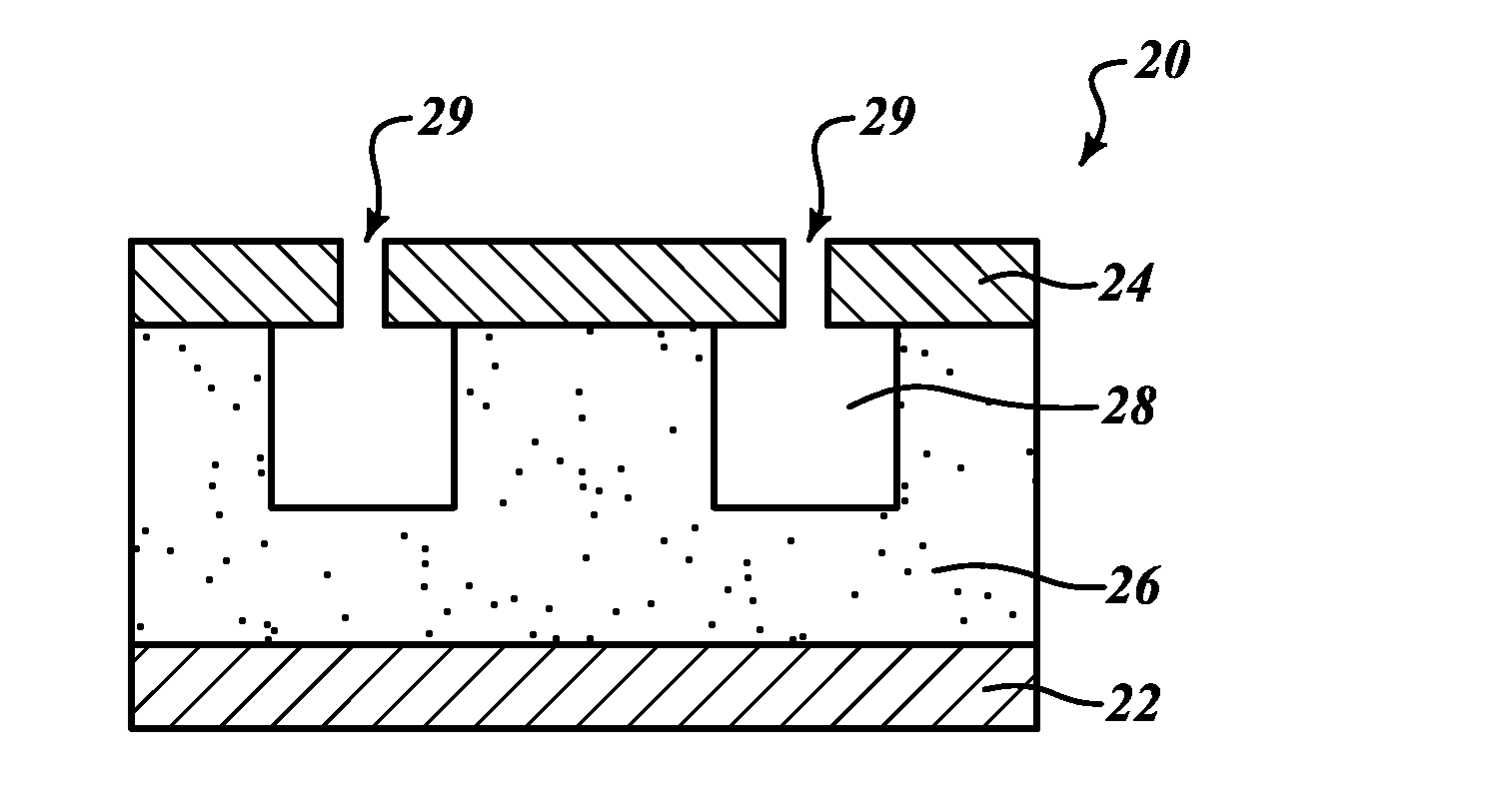
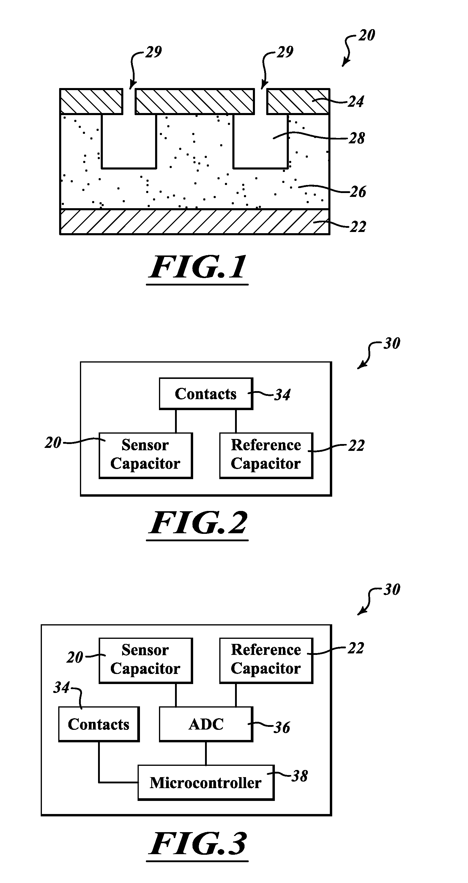
[0031]FIG. 1 illustrates a capacitive humidity center 20 according to one embodiment. The capacitive humidity sensor 20 is a capacitor including a bottom electrode 22 and a top electrode 24. A humidity sensitive dielectric layer 26 is positioned between the bottom electrode 22 and the top electrode 24. Hollow spaces 28 are formed in the humidity sensitive dielectric layer 26. Portions of the hollow spaces 28 are positioned directly between the bottom electrode 22 and the top electrode 24. Openings 29 are formed in the top electrode 24.

[0032]The capacitive humidity sensor 20 outputs a capacitance signal indicative of the humidity in the surrounding environment. The capacitance of a capacitor varies according to the following relationship:

C˜∈×A / d

where C is the capacitance, ∈ is the dielectric constant of the dielectric material between the electrodes of the capacitor, A is the area of overlap of the electrodes of the capacitor, and d is the distance between the electrodes of the capa...


PUM

PropertyMeasurementUnit
Thicknessaaaaaaaaaa
Sensitivityaaaaaaaaaa
Capacitanceaaaaaaaaaa

Abstract

A capacitive humidity sensor includes a first electrode, a humidity sensitive dielectric layer, and a second electrode. The humidity sensitive dielectric layer is between the first and the second electrodes. The humidity sensitive dielectric layer is etched at selected regions to form hollow regions between the first and second electrodes.

Description

BACKGROUND[0001]1. Technical Field[0002]The present disclosure relates to the field of humidity sensors. The present disclosure relates in particular to a capacitive humidity sensor.[0003]2. Description of the Related Art[0004]Humidity sensing is important in many fields. In many applications it is beneficial to control the humidity level. In other applications it is beneficial simply to know what the humidity level is. In many manufacturing settings it is important that the relative humidity not rise above a certain level or the products being manufactured may be adversely affected. In many scientific settings the relative humidity is taken into account while performing experiments. When processing certain types of integrated circuits the humidity level may be closely monitored or controlled both in the clean room settings as well as in the various deposition chambers and processing equipment.[0005]Humidity sensors come in a variety of forms. Humidity sensors can include resistive ...

Claims


Application Information

Patent Timeline
IPC IPC(8): G01N27/22B05D3/10C23F1/02B05D5/12
CPCG01N27/223
Inventor LE NEEL, OLIVIERCHERIAN, SUMANSHANKAR, RAVIPOH, BOON NAMMARSANNE, SEBASTIENVAIANA, MICHELE
Owner STMICROELECTRONICS SRL
Features
  • Generate Ideas
  • Intellectual Property
  • Life Sciences
  • Materials
  • Tech Scout
  • Unparalleled Data Quality
  • Higher Quality Content
  • 60% Fewer Hallucinations
Learn More