Unlock instant, AI-driven research and patent intelligence for your innovation.

Position detector and position detection method

a technology of position detector and detection method, which is applied in the field of position detector, can solve problems such as adverse effects, and achieve the effects of reducing the level of transmission signal supplied, good s/n, and increasing the level of transmission signal

Active Publication Date: 2013-06-06
WACOM CO LTD
View PDF2 Cites 5 Cited by
  • Summary
  • Abstract
  • Description
  • Claims
  • Application Information

AI Technical Summary

Benefits of technology

This patent describes a position detector that can detect the position of both an electronic pen and a finger or capacitive pen using a single detector. The detector includes two sensors: one based on electromagnetic induction and the other based on capacitance. The position of the indicator (either the electronic pen or the finger / capacitive pen) is detected based on the level of the electromagnetic induction signal or the change in current from the sensor's reception electrode. The detector can control the level of the transmission signals supplied to the sensors in such a way that reduces the impact on the electromagnetic induction detector and improves the capability to detect the position indicated by the indicator.

Problems solved by technology

As a result, a position indicator having two position detection sensors, one based on electromagnetic induction and the other based on capacitance, so as to be capable of simultaneously detecting the positions indicated by indicators with the two sensors, may suffer adverse effects including jitter in the position detection signal obtained from the electromagnetic induction position detection circuit caused by the transmission signal supplied to the capacitive position detection sensor.

Method used


Image

  • Position detector and position detection method
  • Position detector and position detection method
  • Position detector and position detection method

Examples


first embodiment

[0043]FIG. 1 is an exploded perspective view illustrating a configuration example of an electronic device incorporating a first embodiment of a position detector according to the present invention. In the example shown in FIG. 1, the electronic device is a pad type terminal that has not only the capability to detect the position indicated by an electromagnetic induction indicator, for example, a position indicator such as an electronic pen (hereinafter referred to as the first indicator) with an electromagnetic induction position detection sensor (hereinafter referred to as the first sensor), but also the capability to detect the position on the display screen of a display device indicated by an indicator such as a finger or a position indicator (a capacitive pen) (hereinafter referred to as the second indicator) with a capacitive position detection sensor (hereinafter referred to as the second sensor). The electronic device can simultaneously detect the positions indicated by the f...

second embodiment

[0113]In the first embodiment, the level of only the transmission signal supplied to the second sensor 40 is controlled to alleviate jitter in the electromagnetic induction first sensor 20 and position detection circuit 200.

[0114]However, it is possible to more effectively reduce adverse effects of the transmission signal supplied to the capacitive second sensor 40 on the electromagnetic induction position detection circuit 200 by controlling not only the level of the transmission signal supplied to the second sensor 40 but also the level of the electromagnetic induction signal supplied from the first sensor 20 to the electronic pen 23 as a position indicator constituting the first indicator.

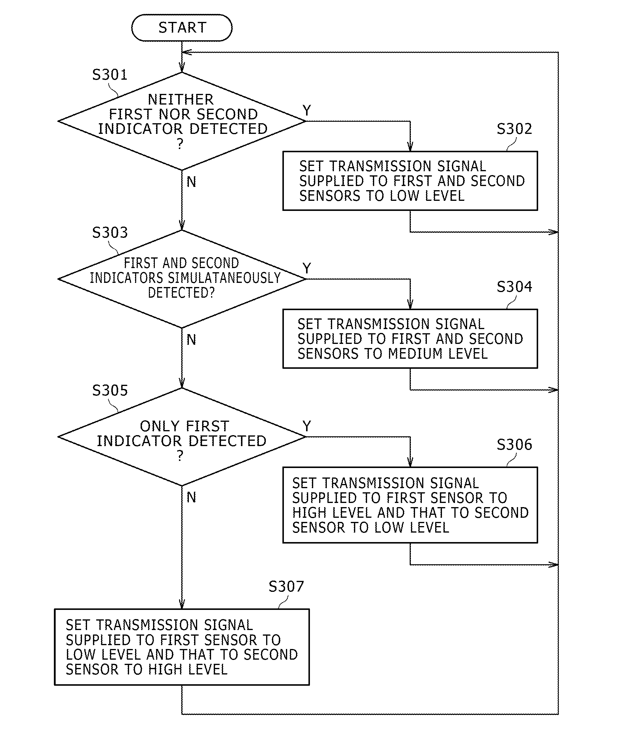
[0115]The position indicator according to the second embodiment is identical in hardware configuration to the counterpart according to the first embodiment. Further, in the second embodiment, the control circuit 410 of the position detection circuit 400 controls the transmission signal level as ...

third embodiment

[0131]The third embodiment is a modification example of the second embodiment. That is, in the second embodiment described above, the control circuit 210 of the position detection circuit 200 and the control circuit 410 of the position detection circuit 400 each includes the capability of a position indication state determination circuit, and they generate the control codes CP1 and CP2 separately.

[0132]In contrast, in the third embodiment, a control code generation circuit having a position indication state determination circuit is provided separately from the position detection circuits 200 and 400, thus reducing the processing burden on the control circuits 210 and 410.

[0133]FIG. 9 illustrates major sections of a hardware configuration example of the position detection circuit of the electronic device 10 according to the third embodiment. The third embodiment is identical in configuration to the first and second embodiments described above except for the illustrated major sections...


PUM


Abstract

In a position detector having two sensors, a first sensor detects a position indicated by a first indicator by electromagnetic induction and a second sensor detects a position indicated by a second indicator by a detection method other than electromagnetic induction. The position detector reduces adverse effects of the transmission signal supplied to the second sensor on the electromagnetic induction position detection circuit. The position indication state of the first and second indicators is determined based on a signal output from the first sensor according to the position indication by the first indicator on the first sensor and a signal output from the second sensor according to the position indication by the second indicator on the second sensor. According to the determination results of the position indication state, the level of the transmission signal provided to the second sensor to detect the position indication by the second indicator is controlled.

Description

CROSS-REFERENCE(S) TO RELATED APPLICATION(S)[0001]The present application claims priority under 35 U.S.C. 119(a) of Japanese Application No. 2011-264871, filed Dec. 2, 2011, the entire content of which is incorporated herein by reference.TECHNICAL FIELD[0002]The present invention relates to a position detector having a first sensor that detects a position indicated by a first indicator through electromagnetic induction and a second sensor that detects a position indicated by a second indicator through a detection method other than electromagnetic induction so that it can simultaneously detect the positions indicated by the first and second indicators.BACKGROUND ART[0003]Position detectors designed to detect the position indicated by an indicator such as a finger or a pen are known. A variety of position detection methods including resistance film method, electromagnetic induction method, and capacitance method are applicable for such position detectors.[0004]Of those various types, ...

Claims


Application Information

Patent Timeline
Patent Type & Authority Applications(United States)
IPC IPC(8): G01B7/14
CPCG06F3/0416G06F3/046G06F3/044G06F3/0446
Inventor SUZUKI, KEN
Owner WACOM CO LTD
Features
  • R&D
  • Intellectual Property
  • Life Sciences
  • Materials
  • Tech Scout
  • Unparalleled Data Quality
  • Higher Quality Content
  • 60% Fewer Hallucinations
Learn More