
Visual Aid For Landing Helicopters

a helicopter and visual aid technology, applied in the direction of instruments, aircraft traffic control, construction, etc., can solve the problems of difficult depth perception perspective to accurately locate the corners of the landing zone, the flashing of five lights can be confusing for the pilot, and the flashing of a xenon strobe is extremely shor

Active Publication Date: 2013-06-06
MCDERMOTT DAMIEN
View PDF25 Cites 19 Cited by
  • Summary
  • Abstract
  • Description
  • Claims
  • Application Information

AI Technical Summary

Benefits of technology

The patent text describes a landing zone kit for helicopters that is designed to provide a temporary landing zone for emergency medical evacuation purposes. The kit must be bright enough to be easily visible from a distance, but must also resist being displaced or overwhelming the pilot with too much light. The kit includes lights that are designed to be seen at night and must not blind the pilot's unaided eye or overwhelming night vision goggles. The kit also includes a reflectorized weighted base backup system to ensure the pilot has an adequately identified landing zone in the event of failure of one or more of the lights in the kit. The kit must be compact and lightweight but still provide adequate visibility for daytime or bright sunlight landings.

Problems solved by technology

This flashing of five lights can be confusing to the pilot.
Furthermore the duration of the flash of a xenon strobe is extremely short making it difficult from a depth perception perspective to accurately locate the corners of the landing zone.
Five flashing lights each having an extremely short flash duration can confuse a pilot or at the very least make it difficult for the pilot to precisely and quickly locate the landing zone.
The small projected area of these weights—when viewed from above—does not provide useflul visibility during daytime operations.
This design offers little wind resistance because of its low profile and small size.
Unfortunately the low profile of the lights substantially reduces their visibility if they are surrounded by tall grass.
This first prior art kit creates a number of difficulties for pilots.
This causes a problem for pilots flying with night vision goggles which respond to both visible and infrared light.
The flashing of five lights within the landing zone can both blind and confuse the pilot.
Since this first kit illuminates all five lights with a single color it opens the door to pilot error as the pilot may confuse the wind direction light with the perimeter lights.
However it still does not permit the pilot to distinguish between the perimeter lights and the wind direction light.
In addition if the five steady beam light modules are employed the pilot can fail to locate the landing zone which now can be confused with other steady lights in the area.
Since the lights and bases are permanently connected there is no way to deploy the bases separately for daytime landings.
The bases are not large enough to provide reasonable visibility to an approaching pilot and not coated with fluorescent paint which would be employed if bright sunlight visibility were an objective.
This is undesirable as the base / light assembly can be displaced.
Due to its round perimeter the base can roll to an undesirable location.
This design is not a desirable result as it increases the wind resistance and positions the center of gravity of the design substantially above ground level decreasing the stability of the assembly.
Additional weight can be added to correct the stability problem but additional weight is not desirable when transporting the LZ kit.
Hence it is usually inefficient and sometimes impossible to change the color of the emitted light from an LED light source by changing a lens or filter.
However pilots flying with some night vision goggles can have a serious problem as some goggles attenuate light at the wavelengths represented by blue LED lights.
Pilots using some filtered night vision goggles will have trouble seeing the blue LED wind direction lights as the blue wavelengths are blocked and the LED lamps emit very little infrared light.
This is problematic as knowing wind direction is critical to a safe landing and takeoff.
The military is known to have its own requirements, so what works for them, may not be acceptable for civilian pilots.
For example, civilians may not have available rocks to prevent the fabric from being blown away.
Also the lights are not bright enough for the civilian world in which the lights marking the landing zone have to compete with nearby civilian lighting.
Finally, although the fabric is coated with fluorescent orange and reflective paints it does not stand out or provide the visibility of a smooth, flat fluorescent orange or reflective surface because the wrinkled fabric reduces the visibility of both the fluorescent orange and reflective paints.
Therefore a group of these markers—as would be required in a landing zone kit—would be unacceptably bulky when considered for civilian use.
The reduced weight option is especially important for designs which axially position the batteries because axially positioned designs tend to have their center of gravity high making them unstable.
Pilots flying with night vision goggles cannot differentiate between colors.
Therefore, using colors to separate wind direction from perimeter lights will not function for pilots flying with night vision goggles.
This is done because even though five flashing lights can be distracting and confusing some pilots prefer flashing lights in city areas to differentiate the landing zone from steady beam surrounding lighting.
Space is valuable and a landing zone kit which is too bulky or heavy will not be acceptable.

Method used


Image

  • Visual Aid For Landing Helicopters
  • Visual Aid For Landing Helicopters
  • Visual Aid For Landing Helicopters

Examples


Embodiment Construction

FIGS. 1-12

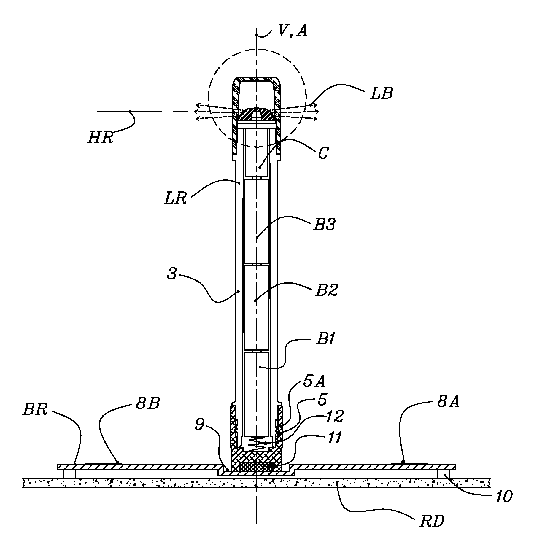
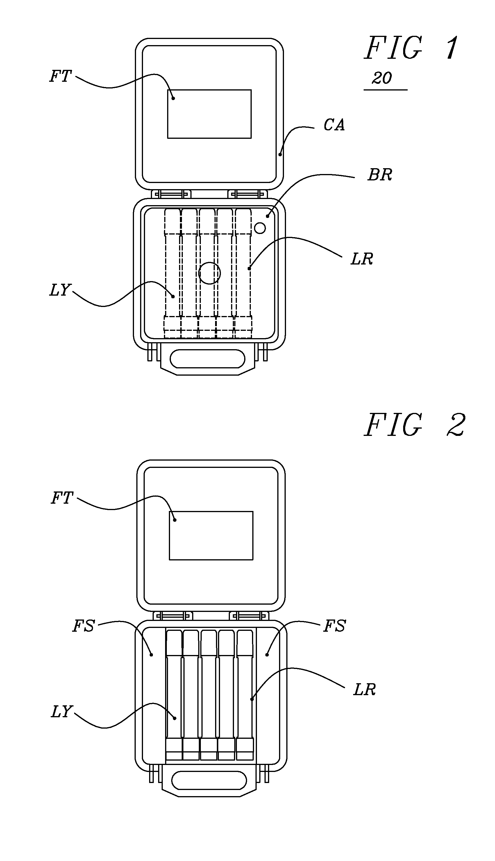
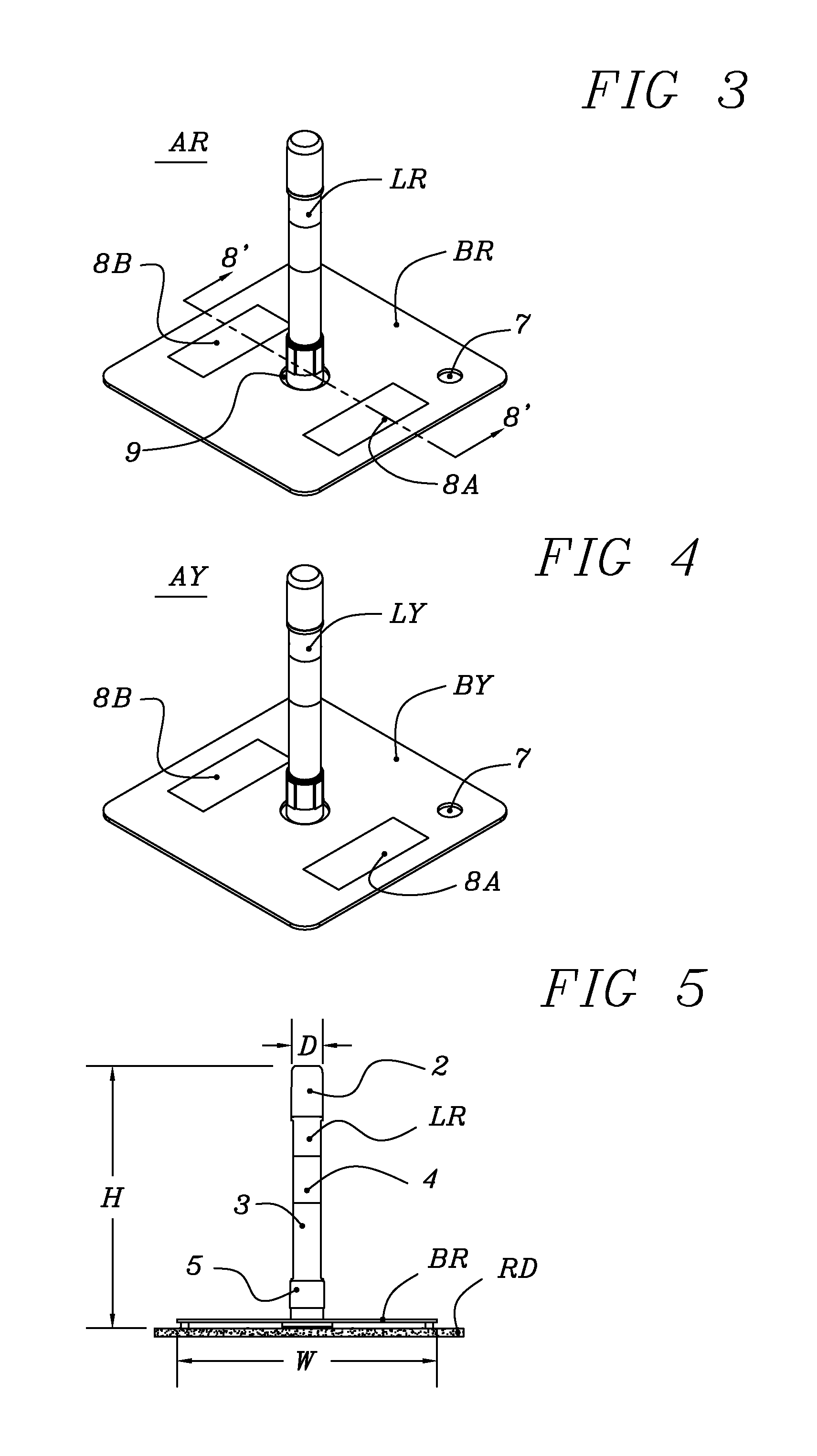
[0045]FIG. 1 is a top view of landing zone kit 20 the preferred embodiment of this invention, Landing zone kit 20 is a visual aid for landing helicopters. Landing zone kit 20 includes four red bases BR, four red lights LR, one yellow base BY and one yellow light LY all packaged in carrying case CA. Carrying case CA is a typical commercially available rectangular or possibly square hinged heavy-duty carrying case. It is sized to secure and provide compact storage for the components of landing zone kit 20.

[0046]FIG. 2 is similar to FIG. 1 except the weighted bases have been removed. Looking at FIG. 2 the five lights are positioned at the bottom of the carrying case with foam side FS on each side of the lights added to prevent shifting. Foam side FS is minimized to minimize the size of carrying case CA. When packaging the kit the five weighted bases are placed on top of the five lights. Foam top FT is glued to the inside top of carrying case CA to prevent movement of the cont...


PUM


Abstract

A visual aid for landing helicopters includes a plurality of weighted bases and a plurality of lights designed such that they can identify a helicopter landing zone during nighttime or during the bright sunlight. The components of the visual aid are designed to provide rapid identification of the landing zone, whether the pilot of the helicopter is flying with his unaided eye or with typical night vision goggles. The weighted bases have a large surface area and are coated with a highly visible fluorescent paint. The lights are designed to emit light having wavelengths, intensities and beam patterns which will not overwhelm night vision goggles but which will be acceptably visible to pilots flying without night vision goggles. The lights and weighted bases are color-coded such that they identify both the perimeter of the landing zone and the wind direction within the landing zone.

Description

BACKGROUND OF THE INVENTION[0001]1. Field of Invention[0002]The field of the invention relates to a landing zone (LZ) kit used to provide a temporary landing zone for helicopters. In order for this kit to do its job properly it must indicate to the pilot the location of the landing zone during both daytime and nighttime conditions. In addition, during the landing process the helicopter generates substantial wind. Therefore the deployed components of the landing zone kit must resist being displaced from their proper locations by the rotor wash of the helicopter. In order to minimize displacement it is important that the components resist rolling on the ground or becoming airborne and striking the helicopters blades.[0003]During nighttime landings pilots often employ night vision goggles to aid them during the landing process. Therefore the landing zone kit must be designed to avoid overwhelming or blinding the night vision goggles being employed. The landing zone kit will overwhelm n...

Claims


Application Information

Patent Timeline
IPC IPC(8): B64F1/18
CPCB64F1/18
Inventor MCDERMOTT, KEVIN
Owner MCDERMOTT DAMIEN
Learn More