Pivotable LED lighting apparatus and universal mounting assembly and method

a technology of led lighting apparatus and mounting assembly, which is applied in the direction of lighting and heating apparatus, cycle equipment, lighting support devices, etc., can solve the problems of not being able to adapt to be used in different configurations, the mounting is not easy to adjust, and the mounting is not easy to use, so as to improve power efficiency, reduce the effect of weight and small siz

Inactive Publication Date: 2013-06-06
NOVA SPORT LIGHTS
View PDF4 Cites 16 Cited by
  • Summary
  • Abstract
  • Description
  • Claims
  • Application Information

AI Technical Summary

Benefits of technology

[0007]The present invention provides a lighting apparatus usable with a mobile vehicle such as a bicycle. In one embodiment, the lighting apparatus includes a first housing, which includes a power source such as rechargeable batteries and a switch mechanism. A second housing is also included which is comprised of light emitting elements such as LEDs. The advantages of LEDs are their smaller size and weight, increased power efficiency, durability, longer life and instant on-off capability. The limitation is that the LEDs provide stationary beams and the cyclist could not easily manipulate the emitting angle of the resultant beam. However, the housings in the present invention are connected by a pivoting mechanism, which allows relative movement between the two housings and permits electrical communication between the light emitting diodes and the batteries. The pivoting mechanism allows the lighting apparatus to provide illumination at different emission angles. The switch mechanism further allows for multiple configurations of the LEDs. The LEDs may be selected to all turn on; all turn off, turn on in a predesignated configuration or turn on in a sequential or nonsequential flashing mode.
[0008]The first housing also includes an integral charging port in order to recharge the batteries. The USB charger is integrated into the unit, and therefore obviates the need to externally couple the charger with the light assembly in order to charge the batteries.
[0009]According to one aspect of the present invention, the lighting apparatus is adapted to a universal mounting assembly. The mounting assembly may be interchangeably attached and detached on different bicycles or on different mounting positions on a particular bike. In the prior art, one disadvantage was that each mount was specific to one specific diameter of handlebar due to the fastener assembly. The problem was that the mount was not adaptable to be used in different configurations: on the top or bottom of the handlebars or on the stem. The mounting assembly of the present invention comprises of a polymeric fastener, such as a TPE or rubber strap for example. In one embodiment, various sizes of straps are provided in order to properly fit various sizes of bicycle stems and handlebars. Alternatively, the fastener can be a universal strap with cutouts in preconfigured locations to allow the mounting assembly to be sized to fit various configurations of a mobile vehicle. In the prior art, the fasteners were often cumbersome to use and required additional accessories like screwdrivers to affix the fastener to the bike. The mounting assembly of the present invention requires no additional tools and improves the ease of attaching and detatching the mounting assembly from a mobile vehicle.

Problems solved by technology

The limitation is that the LEDs provide stationary beams and the cyclist could not easily manipulate the emitting angle of the resultant beam.
In the prior art, one disadvantage was that each mount was specific to one specific diameter of handlebar due to the fastener assembly.
The problem was that the mount was not adaptable to be used in different configurations: on the top or bottom of the handlebars or on the stem.
In the prior art, the fasteners were often cumbersome to use and required additional accessories like screwdrivers to affix the fastener to the bike.

Method used


Image

  • Pivotable LED lighting apparatus and universal mounting assembly and method
  • Pivotable LED lighting apparatus and universal mounting assembly and method
  • Pivotable LED lighting apparatus and universal mounting assembly and method

Examples


Embodiment Construction

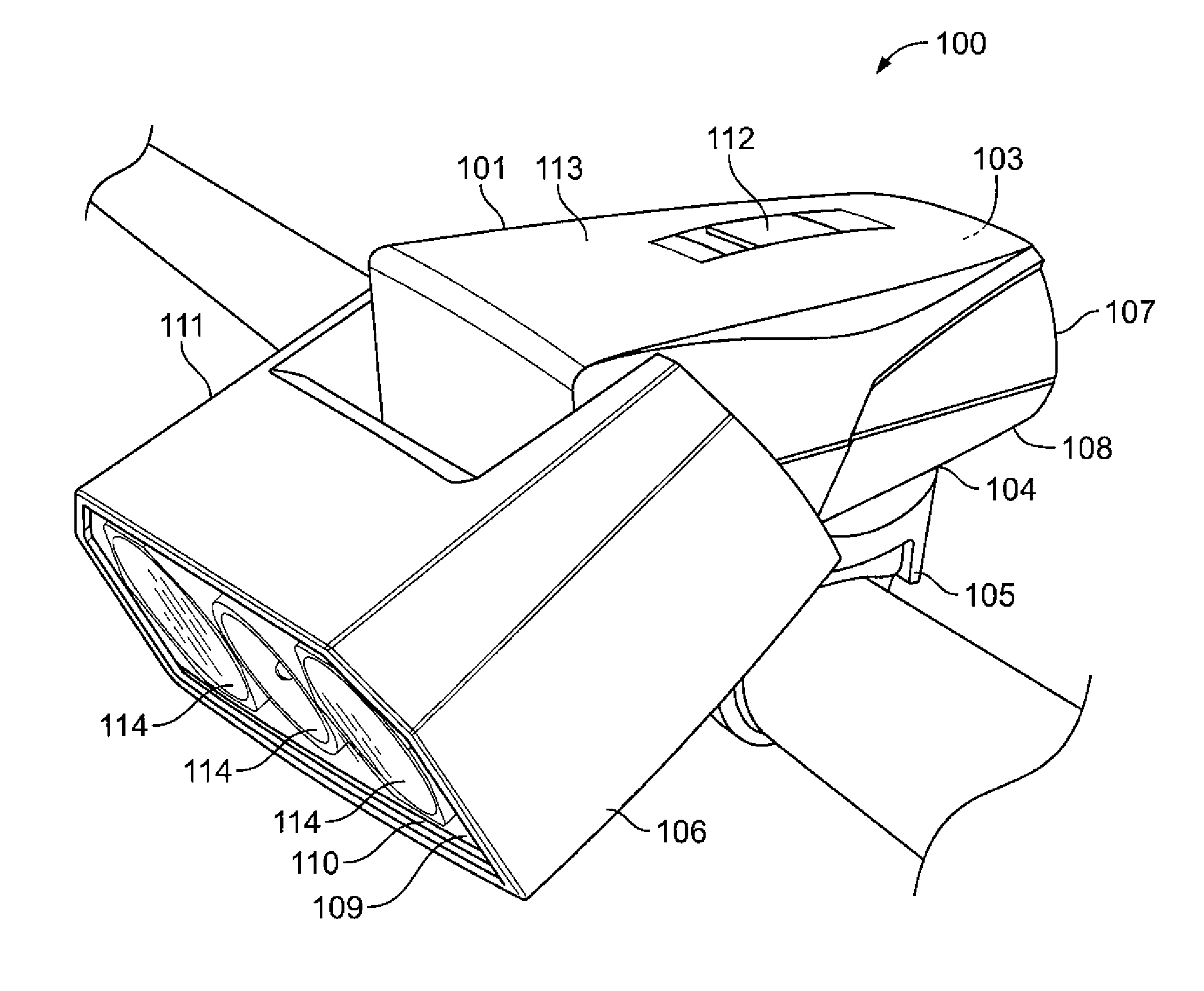
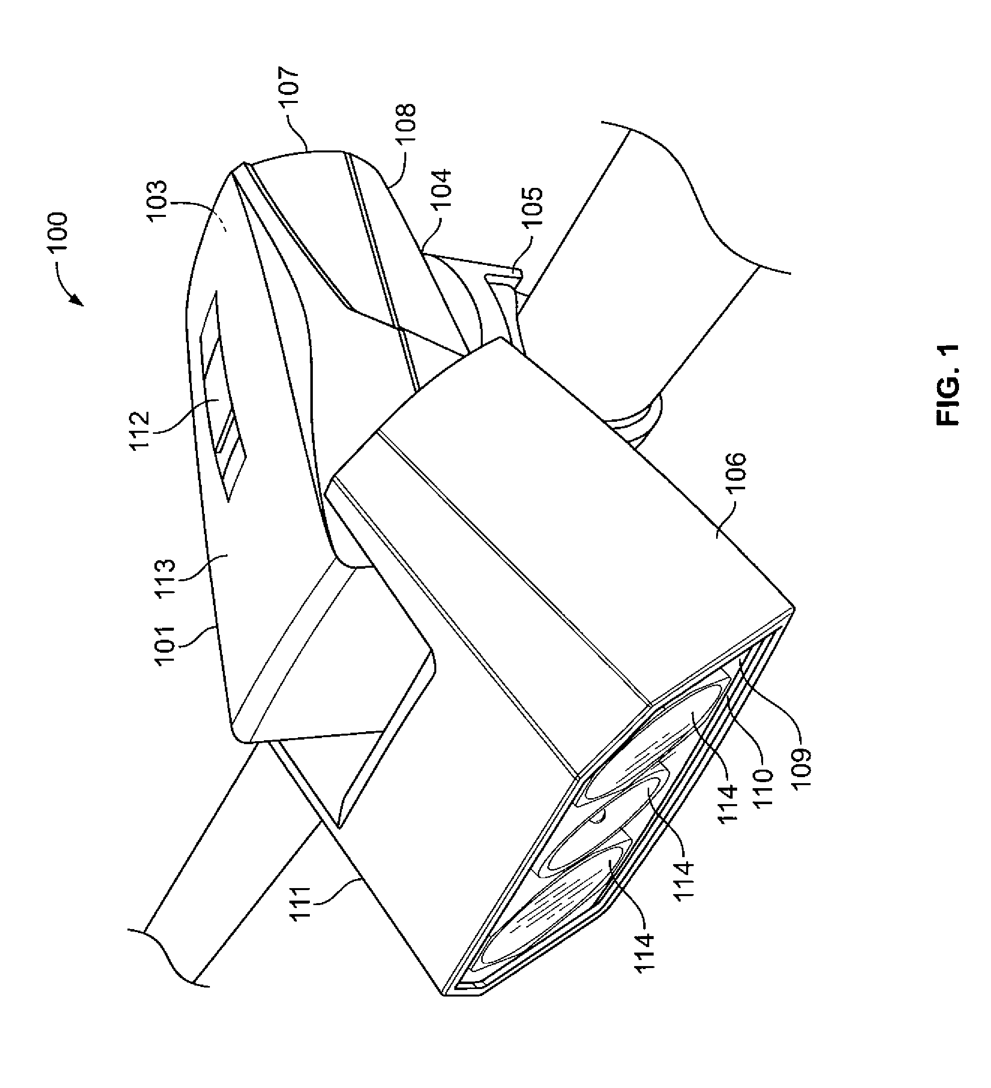
[0031]FIG. 1 shows one embodiment of the lighting apparatus (100) including a first housing 101 which houses rechargeable batteries, such as Li Ion batteries (not shown), and an integral charging port with a flexible cover 103 on a rear vertical surface 107 capable of recharging the batteries. A pedestal 104 is located on a lower horizontal surface 108, for attaching to a universal mounting apparatus 105. A second housing 106 is shown consisting of three 180 lumen light emitting diodes 114 (capable of emitting 180, 360 and 540 lumens), encased in a transparent window 109 on a forward vertical surface 110 and a pivoting mechanism 111 which allows relative pivotal movement between the first and second housings. The pivoting mechanism provides a maximum pivoting angle of 25 degrees vertically above and below the horizontal axis thereby allowing the user to select the desired emission angle of the light. A switch mechanism 112 on an upper horizontal surface 113 provides electrical input...


PUM

PropertyMeasurementUnit
anglesaaaaaaaaaa
emission anglesaaaaaaaaaa
angleaaaaaaaaaa

Abstract

A lighting apparatus usable with a mobile vehicle, which includes first and second housings which contain the power source, the switch mechanism and the light emitting elements therein. A pivoting mechanism allows relative pivotal movement between the two housings thereby allowing the user to manipulate the desired emission angle of illumination. The pivoting mechanism also permits electrical communication between the power source (rechargeable batteries) and the light emitting elements. The lighting apparatus includes an integral charging port for recharging the batteries, such as a micro USB port. The lighting apparatus is adapted to the mobile vehicle by a universal mounting assembly which is configured to be interchangeably attached and detached to fit on different configurations on a particular vehicle. The mounting assembly comprises of a rigid assembly, which attaches the lighting apparatus to the mounting assembly with a flexible fastener to attach the mount to the vehicle.

Description

BACKGROUND OF THE INVENTION[0001]The present invention relates generally to a lighting apparatus and mounting assembly for mobile vehicles, and more particularly to a pivotable light apparatus with light emitting diodes (LEDs), integral USB charger and universal mounting assembly which is mountable in various configurations of a mobile vehicle including the method of illuminating, making and operating the same.[0002]The primary purpose of a light assembly on mobile vehicles such as bicycles is to provide illumination and conspicuity for the cyclist. Light assemblies aid the cyclist in seeing the road ahead of them at times of day and night when there is not enough ambient light to safely ride a bicycle and also allow the cyclist to be seen by oncoming motorists.[0003]In the prior art, light assemblies have used a single beam of light, which limited the field of vision due to the small size of the single beam of light. For cyclists riding at night, particularly at higher speeds, it i...

Claims


Application Information

Patent Timeline
Patent Type & Authority Applications(United States)
IPC IPC(8): F21V21/30H05K13/04F21L4/08
CPCB62J6/02Y10T29/49B62J11/00B62J6/029
Inventor LEONARDO, LUISAGUILERA, OSCAR
Owner NOVA SPORT LIGHTS
Why Eureka
Try Eureka