Cassette system

a cassette and cassette technology, applied in the field of cassette systems, can solve the problems of increasing the power consumption of the cassette, the difficulty of changing the orientation of the cassette, so as to reduce the weight and reduce the weight

Active Publication Date: 2010-08-17
FUJIFILM CORP
View PDF25 Cites 14 Cited by
  • Summary
  • Abstract
  • Description
  • Claims
  • Application Information

AI Technical Summary

Benefits of technology

[0015]It is an object of the present invention to provide a cassette system which includes a cassette having a reduced weight and which has a reduced weight as a whole.
[0017]Since the control unit which includes electronic components is separable from the cassette which includes the radiation detector, the amount of a radiation shield material used to shield the electronic components from the radiation is reduced, with the result that the cassette and the cassette system can be reduced in size and weight. Inasmuch as the cassette itself is small in size and weight, it can easily be placed below the subject, e.g., a patient, when the cassette is to be inserted between the subject and a bed for capturing the radiation image.
[0018]The control unit may comprise a battery for supplying the electric power and a wireless unit for sending the radiation image information to an external control device by way of wireless communications. When the radiation image is to be captured in the cassette, the control unit can easily be changed in attitude. A medium used for the wireless communications may be a radio wave sent and received by antennas, light emitted by LEDs or sound waves such as ultrasonic waves generated by ultrasonic transducers. If the radio wave sent and received by antennas is used, then the control unit may be changed in attitude to cause the directivity of the antenna on the control unit to match the directivity of the antenna on the external control device. As the transmission and reception sensitivity of the antennas for the radio wave is increased, the consumption of electric power stored in the battery is reduced.
[0019]The cassette and the control unit may be detachably connected to each other by a cable and at least one connector. Therefore, the cassette and the control unit can be handled with ease. If the connector is mounted on the cassette, then since the cassette is basically made up of the radiation detector, the connector, and a casing which houses them, the space in the casing is effectively utilized.
[0020]The cassette system may further comprise a take-up mechanism mounted on the control unit for winding up the cable such that the cable can be reeled out from the take-up mechanism. The cable may thus easily be accommodated in the control unit.
[0023]According to the present invention, since the control unit including the electronic components is separable from the cassette including the radiation detector, the amount of an X-ray shield material used to shield the electronic components from the X-rays is reduced, with the result that the cassette and the cassette system can be reduced in size and weight.

Problems solved by technology

The technology disclosed in Japanese Laid-Open Patent Publication No. 2004-173907 is undesirable because the cable 302 connected to the cassette 306 is awkward when the cassette 306 is carried around.
The increased intensity of the radio wave transmitted from the antenna of the cassette necessarily results in an increase in the power consumption of the cassette.
Particularly, after the cassette disclosed in Japanese Patent No. 3494683 is set between the patient and the bed, it is difficult to change the orientation of the cassette for increasing the transmission and reception sensitivity of the cassette and the controller.
If the patient on the bed is seriously ill or an aged person, then it is all the more difficult to change the orientation of the cassette.
When X-ray images are recorded in the cassettes disclosed in Japanese Laid-Open Patent Publication No. 2004-173907, Japanese Patent No. 3494683, and Japanese Laid-Open Patent Publication No. 2003-248060, the electronic components thereof tend to be deteriorated or damaged by direct exposure to the X-rays.
However, since the lead plate is heavy, it makes the cassette also heavy as a whole.

Method used


Image

  • Cassette system
  • Cassette system
  • Cassette system

Examples


Embodiment Construction

[0038]Like or corresponding parts are denoted by like or corresponding reference characters throughout views.

[0039]Cassette systems according to preferred embodiments of the present invention, which are used in combination with radiation image capturing systems, will be described in detail below with reference to the accompanying drawings.

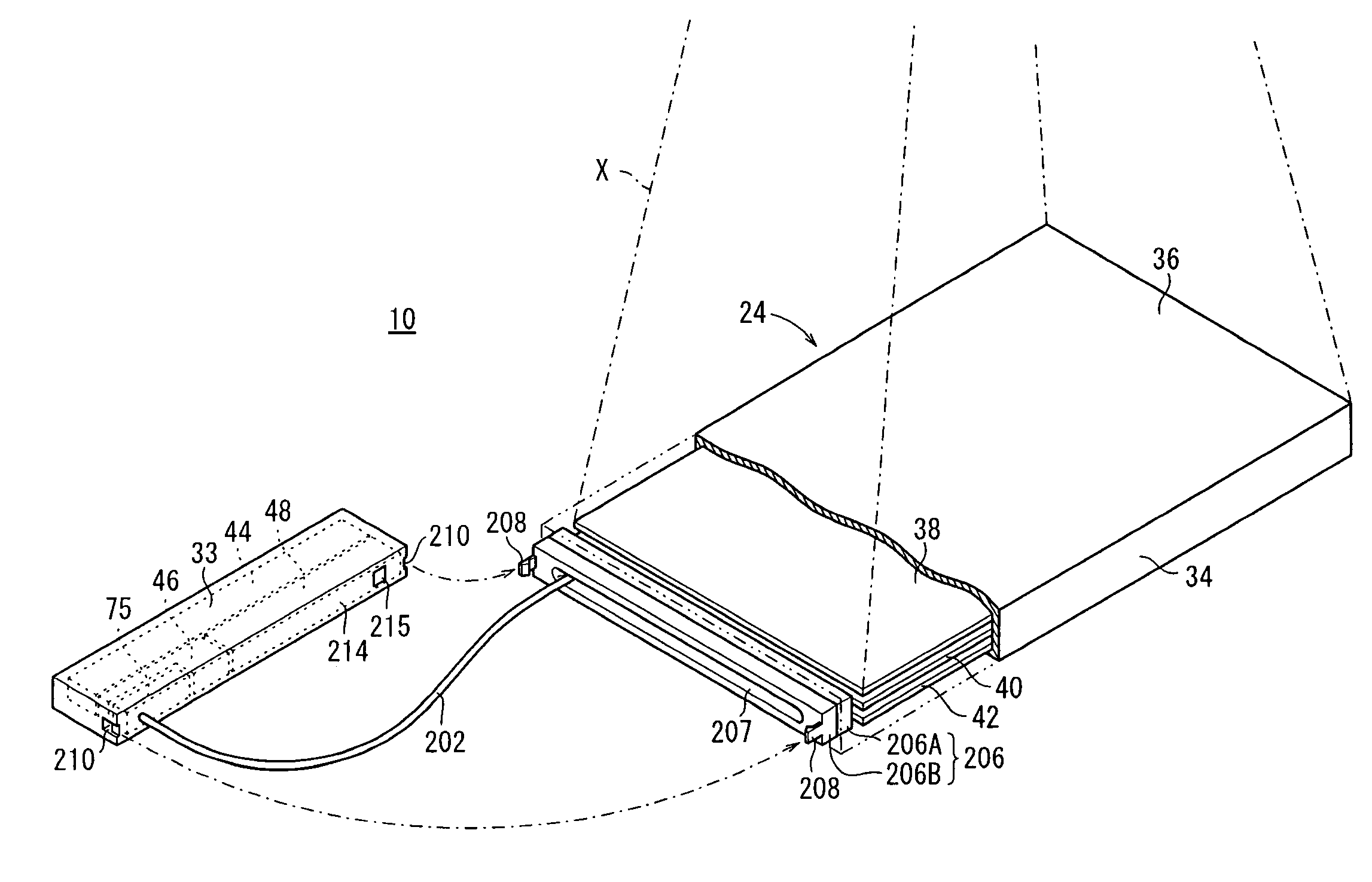
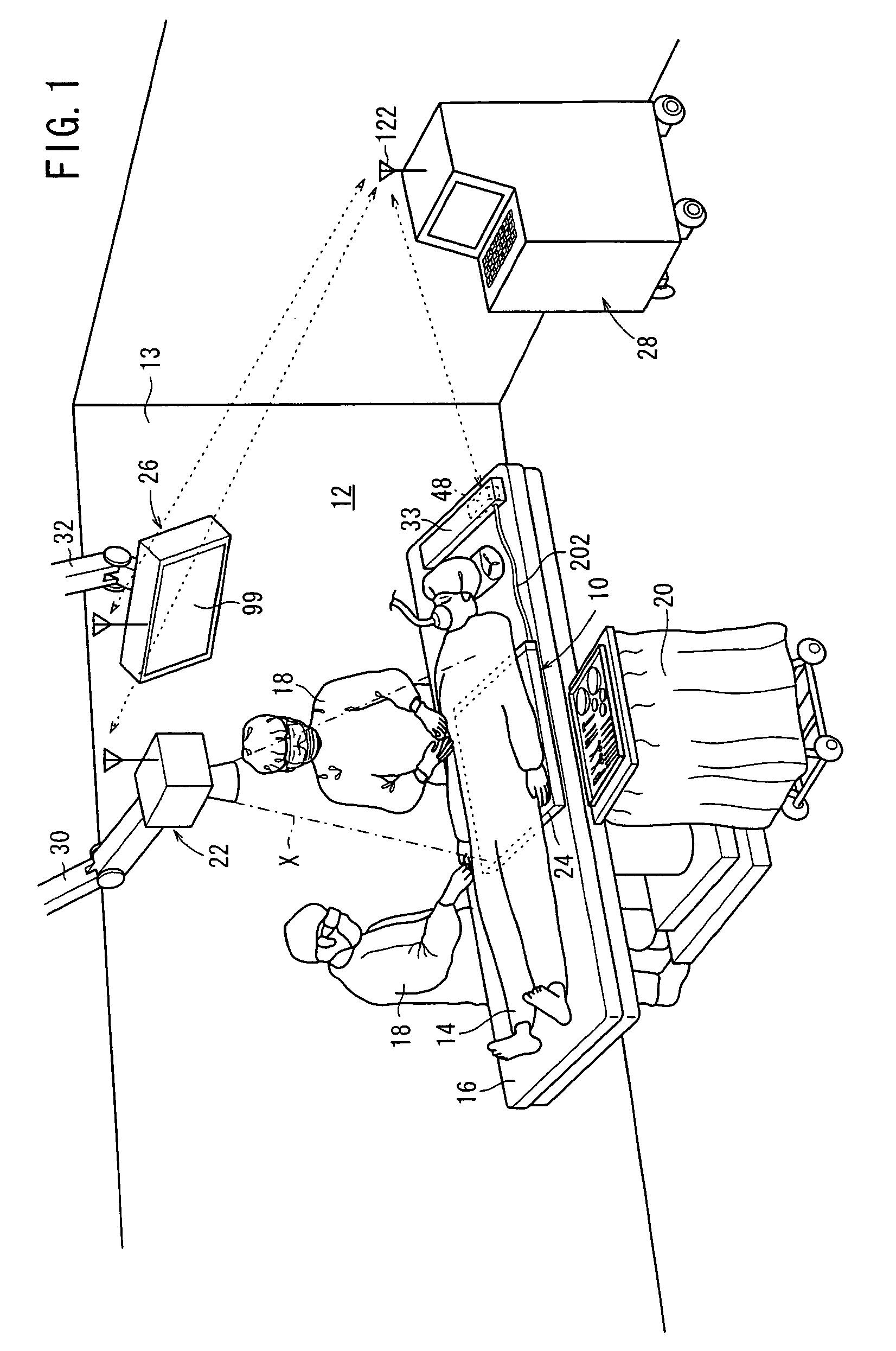
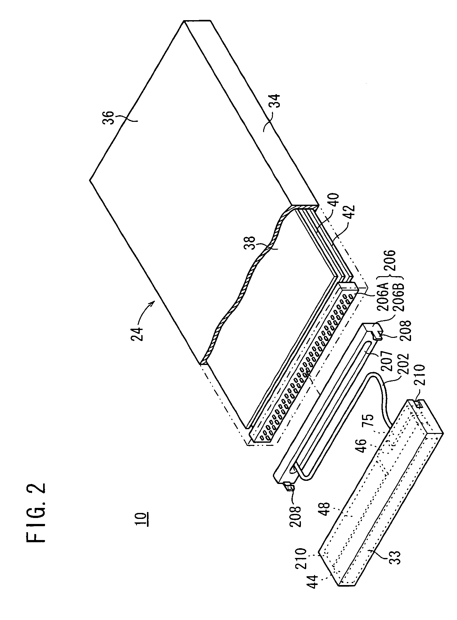
[0040]FIG. 1 shows in perspective an operating room 13 incorporating a radiation image capturing system 12 which employs a cassette system 10 according to an embodiment of the present invention. As shown in FIG. 2, the cassette system 10 comprises a cassette 24 and a control unit 33 connected to the cassette 24 by a cable 202.

[0041]The operating room 13 has, in addition to the radiation image capturing system 12 which employs the cassette system 10, a surgical table 16 for a patient 14 to lie thereon, and an instrument table 20 disposed to one side of the surgical table 16 for placing thereon various tools and instruments to be used by surgeons 18 ...


PUM


Abstract

A lightweight cassette system comprises a cassette for detecting radiation image and a control unit for communicating with a console, the control unit being connected to the cassette. The control unit, which includes electronic components such as an interface circuit, a cassette controller, and a communication unit, is separably connected to the cassette which includes a radiation detector by connectors and a cable.

Description

CROSS-REFERENCE TO RELATED APPLICATIONS[0001]The present application claims priority from Japanese Patent Application Nos. 2007-230767, filed Sep. 5, 2007, and 2008-195690, filed Jul. 30, 2008, the contents of both of which are herein incorporated by reference in their entirety.BACKGROUND OF THE INVENTION[0002]1. Field of the Invention[0003]The present invention relates to a cassette system having a radiation detector for detecting a radiation that has passed through a subject and converting the detected radiation into radiation image information.[0004]2. Description of the Related Art[0005]In the medical field, there have widely been used radiation image capturing apparatus which apply a radiation to a subject and guide the radiation that has passed through the subject to a radiation detector so as to capture a radiation image from the radiation. Known forms of the radiation detector include a conventional radiation film for recording a radiation image by way of exposure, and a sti...

Claims


Application Information

Patent Timeline
Patent Type & Authority Patents(United States)
IPC IPC(8): G01T1/24
CPCA61B6/00A61B6/4233A61B6/563A61B6/4488A61B6/467A61B2560/0456A61B6/4291A61B6/4423
Inventor OHTA, YASUNORIKITO, EIICHITANABE, TSUYOSHIYOSHIMI, TAKUYA
Owner FUJIFILM CORP
Why Eureka
Try Eureka