System and Method for Coherent Frequency Switching in DDS Architectures

a frequency switching and coherent technology, applied in the field of radar systems, can solve the problems of insufficient reflection, insufficient doppler filtering operation processing of receiver signals, inability to cancel clutter, etc., and achieve the effect of small size and weigh

Inactive Publication Date: 2008-03-27
LOCKHEED MARTIN ,
View PDF27 Cites 16 Cited by
  • Summary
  • Abstract
  • Description
  • Claims
  • Application Information

AI Technical Summary

Benefits of technology

[0019]The present invention addresses the needs described above by providing a digital local oscillator implementation that provides stable coherent clock signaling in an implementation that is small in size and weight, and efficient from a power consumption standpoint. The local oscillator of the present invention also provides fine grain tuning resolution without the need for additional components.

Problems solved by technology

If the system is not coherent, the reflections will not add properly.
If the timing signals generated by the oscillator in a subsequent receive period are not coherent with the previous timing signals generated by the oscillator, receiver signal processing related to Doppler filtering operations will not be performed properly.
For example, when the receiver attempts to correlate the return signals with the transmitted waveform, spurious signals may be generated and clutter may not be canceled.
The physical realization is relatively heavy, bulky, and power hungry.
This translates to higher cost.
However, as shown in FIG. 5, the DDS implementation has a major drawback in that it cannot provide multiple coherent frequency signals.
As noted above, the phase ambiguity may prevent the receiver from properly performing Doppler processing, clutter cancellation and correlation filter functions.

Method used


Image

  • System and Method for Coherent Frequency Switching in DDS Architectures
  • System and Method for Coherent Frequency Switching in DDS Architectures
  • System and Method for Coherent Frequency Switching in DDS Architectures

Examples


Embodiment Construction

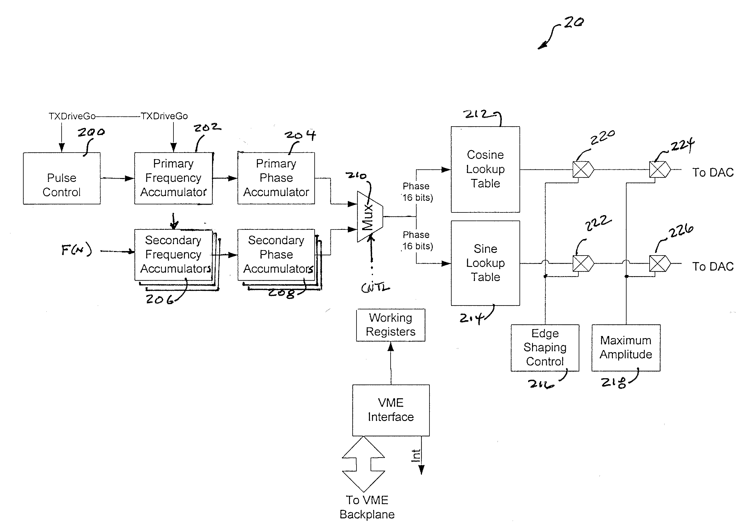
[0031]Reference will now be made in detail to the present exemplary embodiments of the invention, examples of which are illustrated in the accompanying drawings. Wherever possible, the same reference numbers will be used throughout the drawings to refer to the same or like parts. An exemplary embodiment of the coherent digital local oscillator of the present invention is shown in FIG. 6, and is designated generally throughout by reference numeral 20.

[0032]As embodied herein, and depicted in FIG. 6, a digital local oscillator (DLO) 20 in accordance with an embodiment of the present invention is disclosed. It will be apparent to those of ordinary skill in the pertinent art that modifications and variations can be made to DLO 20 of the present invention depending on the implementation of the circuit architecture. For example, DLO 20 may be implemented as an integrated device such as a field programmable gate array (FPGA). Those of ordinary skill in the art will also understand that DLO...


PUM


Abstract

The present invention is directed to an integrated circuit device that includes a primary signal synthesizer configured to generate a free-running first digital frequency signal and at least one secondary signal synthesizer disposed in parallel with the primary signal synthesizer and configured to generate a free-running at least one second digital frequency signal. A switch element includes a first switch input coupled to the primary signal synthesizer and at least one second switch input coupled to the at least one secondary signal synthesizer. The switch element is configured to select a switch output that provides either the free-running first digital frequency signal or the free-running at least one second digital frequency signal based on a switch control input.

Description

BACKGROUND OF THE INVENTION[0001]1. Field of the Invention[0002]The present invention relates generally to radar systems, and particularly to local oscillator implementations in radar systems.[0003]2. Technical Background[0004]The term “radar” is an acronym for the phrase “radio detection and ranging.”A radar, therefore, transmits RF energy and listens for reflected return signals to detect a target and determine a target's location in space. The range is determined by what is commonly referred to in the art as the “radar equation.” When the radar is disposed on a moving platform, such as a ship or an aircraft, target location may be provided as a relative bearing or a true bearing. The relative bearing is the angle of the target relative to the ship's heading, whereas a true bearing is referenced from true north, i.e., it is the sum of the ship's heading and the target angle. If the target is airborne, the target altitude is obtained by multiplying the target range by the sine of t...

Claims


Application Information

Patent Timeline
Patent Type & Authority Applications(United States)
IPC IPC(8): G01S7/28
CPCG01S7/282G06F1/0342G06F1/0335G01S13/28
Inventor ATHERTON, ADAM T.
Owner LOCKHEED MARTIN ,
Why Eureka
Try Eureka