
Method and apparatus for integrating chemical and environmental sensors into an air purification filter through a reusable sensor port

Active Publication Date: 2013-06-13
SCOTT TECH INC
View PDF9 Cites 23 Cited by
  • Summary
  • Abstract
  • Description
  • Claims
  • Application Information

AI Technical Summary

Benefits of technology

The patent is about a device and method for placing a chemical sensor in a filter to monitor its condition and the effectiveness of the filter in a toxic environment. The device can be either disposable or non-disposable, and it can provide an early indication of when the filter is reaching the end of its life, giving users more time to safely complete tasks and avoid contamination. This technology is particularly useful for air purification filters.

Problems solved by technology

Air purifying filters typically do not have an unlimited service life.
Placing chemical sensors within the sorbent bed is problematic, however, because the sensors can undesirably disturb air flow in the filter.
As a result, the sensor may not detect actual impurity concentration for a majority of the air stream, which can result in false signals.
In addition, the presence of the sensor inside the adsorbent bed may adversely affect the air purification outcome and results in shorter service life time of the filter cartridge.
Furthermore, an embedded sensor approach requires that the sensor be disposed along with the cartridge when the service life of the cartridge ends, which greatly increases costs.
Embedding a sensor in the sorbent bed also can increase the chance of improper bed packing.
Further, it may be technically challenging to mount multiple sensors at various bed locations.

Method used


Image

  • Method and apparatus for integrating chemical and environmental sensors into an air purification filter through a reusable sensor port
  • Method and apparatus for integrating chemical and environmental sensors into an air purification filter through a reusable sensor port
  • Method and apparatus for integrating chemical and environmental sensors into an air purification filter through a reusable sensor port

Examples


Embodiment Construction

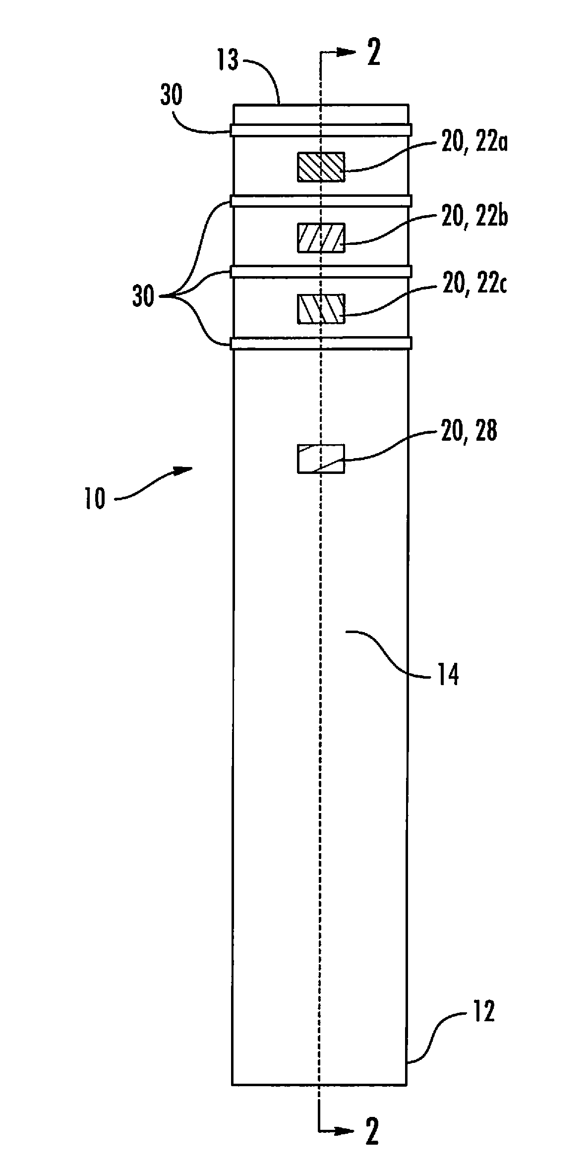
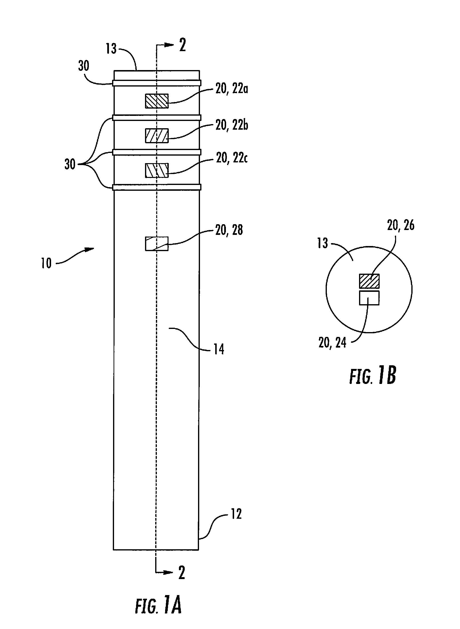
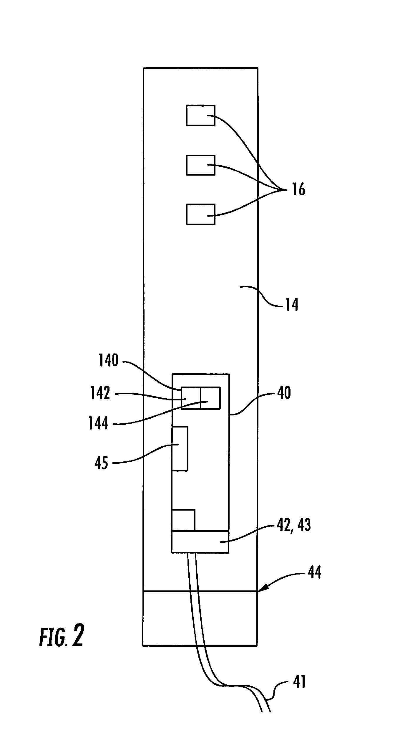
[0021]A device and method are disclosed for providing reusable sensors within a sorbent bed of an air purifying cartridge. Referring to FIG. 1A, the device may be a sensor device, or post, 10 having a hollow cylindrical sensor post housing 14 that supports a plurality of different types of sensors 20 that may be mounted at a variety of positions along the housing 14. In one embodiment, the housing 14 can be mounted to a filter cartridge 60 (FIG. 4) at a lower portion 12 of the housing 14 prior to engagement of the filter cartridge 60 onto a respirator 100. In alternative embodiments, the sensor post housing 14 or sensor 20 includes a mechanical connection for attachment to an inhalation valve support of the respirator 100. Alternatively, the sensor post 10 may be fixed to the filter cartridge 60. Desirably, the sensor post 10 may be positioned within the filter cartridge 60 so that the sensors 20 disposed in or on the sensor post 10 can sense conditions in the sorbent bed 62 of the ...


PUM

PropertyMeasurementUnit
Lengthaaaaaaaaaa
Timeaaaaaaaaaa
Poweraaaaaaaaaa

Abstract

A sensor device is disclosed for providing end of service life indication for an air purification filter. The sensor device has a cylindrical housing for insertion into a sorbent bed of a filter, and can be removed from the bed and reused at the end of the filter service. One or more sensors inside the housing are configured to sense physical / chemical characteristics of air passing through the sorbent bed, and to provide associated data to a sensor conditioning board within the housing. The sensor conditioning board processes the received data and conditions the data as desired. The housing is receivable in a cavity formed in the filter bed. A receiving structure receives the housing therein. Data from the one or more sensors can be used to calculate predicted end of service life of the filter. Other embodiments are described and claimed.

Description

CROSS-REFERENCE TO RELATED APPLICATIONS[0001]This application is a continuation of International Patent Application No. PCT / US2011 / 046199 filed Aug. 2, 2011, which claims the benefit of U.S. Provisional Patent Application No. 61 / 434,755, filed Jan. 20, 2011, and U.S. Provisional Patent Application No. 61 / 371,427, filed Aug. 6, 2010, all of which are incorporated herein by reference in their entirety.FIELD OF THE DISCLOSURE[0002]The present disclosure relates to a method of integrating chemical and environmental sensors into an air purifying filter as an End-of-Service-Life-Indicator (referred to as ESLI hereafter) and / or Residual-Life-Indicator (referred to as RLI hereafter), and more particularly to a sensor post structure for hosting a plurality of sensors that provide residual life indication and end of service life indication for an air purifying cartridge.BACKGROUND OF THE DISCLOSURE[0003]Air purifying filters typically do not have an unlimited service life. End users of air pu...

Claims


Application Information

Patent Timeline
IPC IPC(8): B01D46/00A62B9/02A62B7/10A62B18/10A62B18/02A62B19/00A62B9/00A62B18/08A62B23/02
CPCB01D46/0086A62B23/02B01D46/429B01D46/444B01D46/448B01D46/46B01D53/0454A62B7/10A62B9/006A62B9/02A62B18/02A62B18/088A62B18/10A62B19/00B01D46/2411B01D53/04B01D53/14B01D53/34G01N27/26B01D46/0036B01D53/02B01D53/229
Inventor DING, FRANKQUIRING, AMY E.PARHAM, MICHAEL
Owner SCOTT TECH INC
Learn More