Oil-reserving piston ring

a piston ring and oil-reserving technology, applied in the direction of brake systems, machines/engines, transportation and packaging, etc., can solve the problems of increasing leakage, increasing leakage, and increasing leakage, and achieves good sealing performance, good lubricating properties, and strong sealability

Inactive Publication Date: 2013-06-13
YANG ZENGLI
View PDF4 Cites 6 Cited by
  • Summary
  • Abstract
  • Description
  • Claims
  • Application Information

AI Technical Summary

Benefits of technology

[0047]With the oil-reserving piston ring of the present invention, the piston can be processed with only one piston ring groove. A good sealing performance can be achieved by using only one oil-reserving piston ring.
[0048]The oil-reserving piston ring of the present invention can be applied to the piston-type internal combustion engine and a compressor. The piston and piston ring of the present invention can replace the conventional pistons and the multiple piston rings each having one-piece structure, and have the advantages of good lubricating property, strong sealability and high reliability. For the compressor having ultra-high working pressure, two oil-reserving piston rings may also be used.
[0049]It can be seen that, the present invention provides an oil-reserving piston ring with the total thickness of the assembly of the two piston rings increased, so that the structural strength is enhanced, and the working surface of each wedge ring thereon is arranged with one to three oil-reserving grooves. And, the upper wedge ring is provided with an oil-collecting groove and connecting holes, so as to greatly improve the lubricating property, sealability and reliability of the pi

Problems solved by technology

Conventional piston rings are usually in one-piece structure with an opening and leakage inevitably occurs at the opening.
And, the higher the working pressure is, the more leakage there will be.
As the abrasion increases, the leakage gradually becomes worse.
Thus, the conventional piston ring of one-piece structure with an opening has always been working under leakage, and due to the opening leakage, a lot of power is lost and the efficiency is decreased.
The labyrinth seal can decrease leakage, but can not avoid leakage.
The increase in the number of ring grooves will surely lead to the reduction in the structural strength of the piston.
However, with the increase in the number of piston rings, friction gradually increases.
The increase of each piston ring further deteriorates the lubrication of the upper ring.
Inadequate lubrication is the main cause for the leakage and abrasion at the working surface.
The two-piece assembled piston ring is expected to achieve a complete seal by the assembly of the two pieces, but such expected effect actually is not achieved.
The leakage amount of the leakage channel depends on the size of the opening, and the amount of leakage is intensified with the increasing abrasion.
Hence, an indirect leakage channel is formed; the leakage amount of this channel depends on the si

Method used


Image

  • Oil-reserving piston ring
  • Oil-reserving piston ring
  • Oil-reserving piston ring

Examples


first embodiment

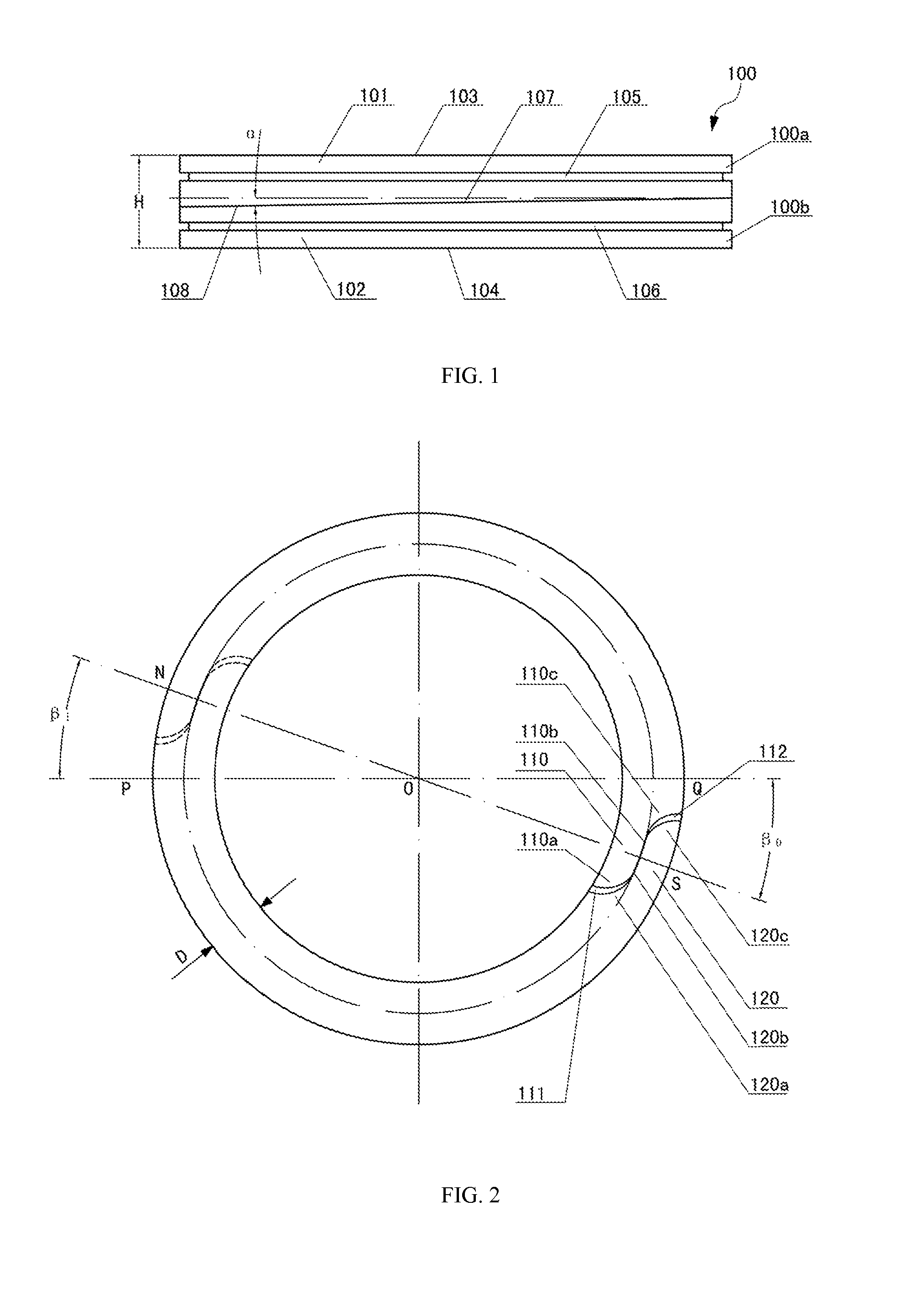
[0064]FIG. 2 is a top view of the oil-reserving piston ring according to the present invention. As shown in FIG. 2, the opening of the upper wedge ring 100a and the opening of the lower wedge ring 100b are staggered away from each other, that is, said two openings are not arranged in the same direction.

[0065]The opening of the upper wedge ring 100a includes an inside overlapping part 110 and an outside overlapping part 120. The inside overlapping part 110 includes an inner projection 110a, an outer recess 110c and a first engaging portion 110b connecting the inner projection 110a with the outer recess 110c. The outside overlapping part 120 includes an inner recess 120a, an outer projection 120c and a second engaging portion 120b connecting the inner recess 120a with the outer projection 120c. The first engaging portion 110b and the second engaging portion 120b are engaged to form a seal.

[0066]Further, as shown in FIG. 2, the inner protrusion 110a and the outer recess 110c of the ins...

second embodiment

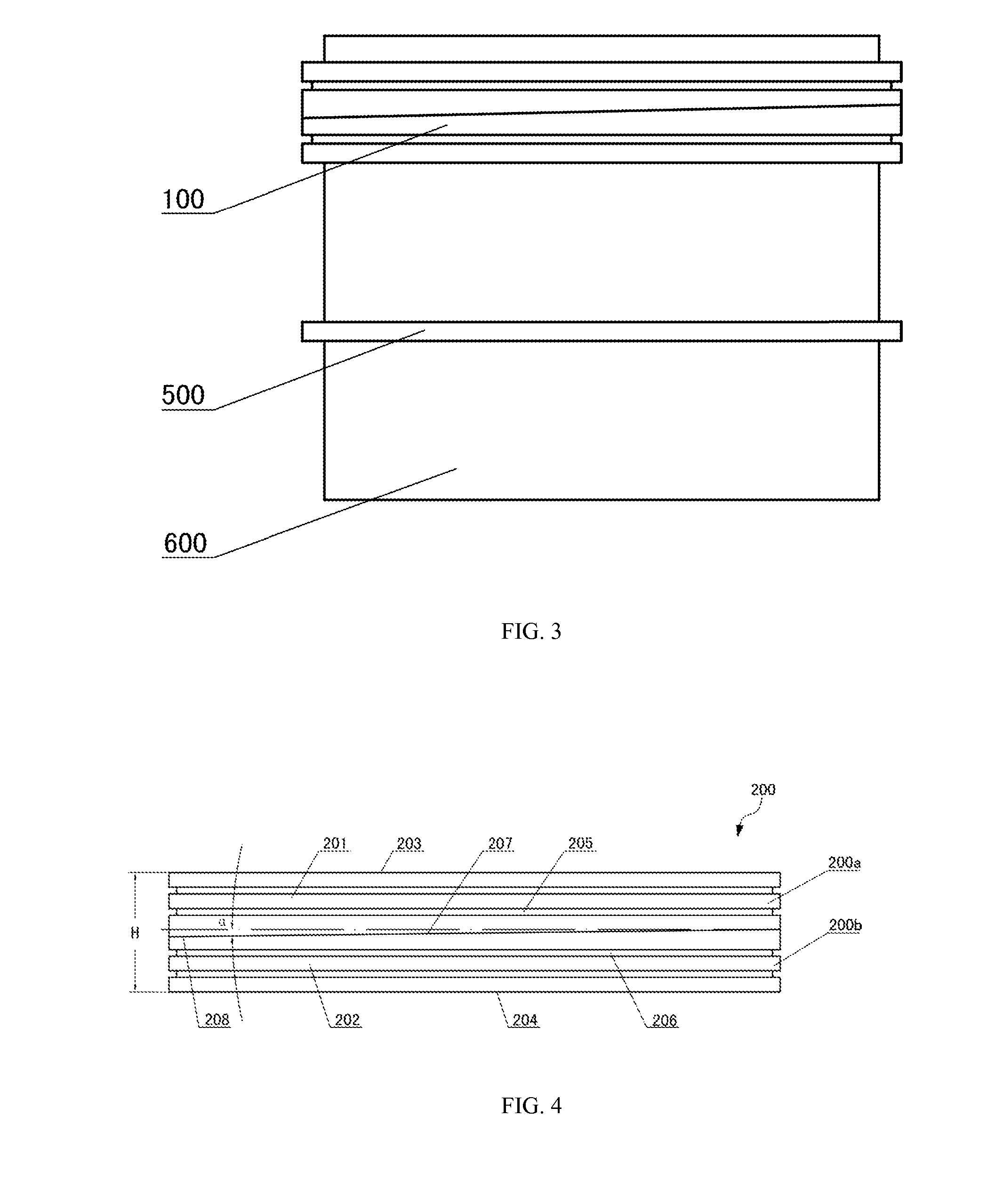
[0076]As described in the background art, the piston ring pumps oil in the piston ring groove. Due to oil pumping, the lubricating oil runs into the combustion chamber and finally forms deposited carbon. In order to solve such problem, the present invention is designed.

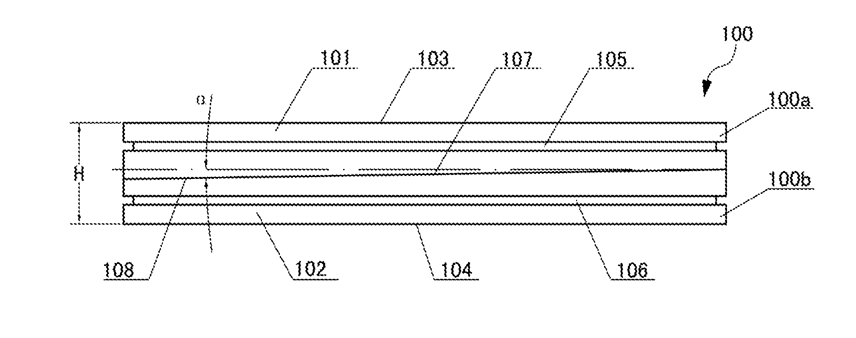
[0077]FIG. 4 is a front view of the oil-reserving piston ring according to the second embodiment of the present invention. As shown in FIG. 4, according to the second embodiment of the present invention, the oil-reserving piston ring 200 includes an upper wedge ring 200a and a lower wedge ring 200b engaged with each other. The upper wedge ring 200a is provided with an opening, and has a first working surface 201 contacting with the wall of a cylinder. The lower wedge ring 200b is provided with an opening, and has a second working surface 202 in contact with the wall of a cylinder. The first working surface 201 is provided with two oil-reserving grooves 205, and the second working surface 202 is provided with two oil-r...


PUM


Abstract

An oil-reserving piston ring includes an upper wedge ring (100a,200a) and a lower wedge ring (100b,200b) jointed with each other. The upper wedge ring (100a,200a) and the lower wedge ring (100b,200b) are each arranged with an opening, the upper wedge ring (100a,200a) has a first working surface (101,201) contacting with the wall of a cylinder, the lower wedge ring (100b,200b) has a second working surface (102,202) contacting with the wall of the cylinder, and at least one of the first working surface (101,201) and the second working surface (102,202) is arranged with at least one oil-reserving groove (105,106,205,206). Also provided is a piston (600) with only one piston ring slot which is used for arranging the oil-reserving piston ring. The oil-reserving piston ring has a good lubricating property and seal, and is high in reliability.

Description

CROSS-REFERENCE TO RELATED APPLICATIONS[0001]This application is a National Stage of International Patent Application No. PCT / CN2010 / 001269, filed Aug. 20, 2010, the content of which is incorporated herein by reference in its entirety.TECHNICAL FIELD[0002]The present invention relates to a piston ring for an internal combustion engine, particularly an oil-reserving piston ring.BACKGROUND ART[0003]Conventional piston rings are usually in one-piece structure with an opening and leakage inevitably occurs at the opening. And, the higher the working pressure is, the more leakage there will be. As the abrasion increases, the leakage gradually becomes worse. Thus, the conventional piston ring of one-piece structure with an opening has always been working under leakage, and due to the opening leakage, a lot of power is lost and the efficiency is decreased.[0004]In order to solve the leakage problem of the conventional piston ring with an opening, multiple piston rings are usually adopted so...

Claims


Application Information

Patent Timeline
IPC IPC(8): F02F5/00
CPCF02F5/00F16J9/16F16J9/14F16J9/20
Inventor YANG, ZENGLI
Owner YANG ZENGLI
Why Eureka
Try Eureka