
Input interface, portable electronic device and method of producing an input interface

a portable electronic device and input interface technology, applied in the field of input interfaces, can solve the problems of increasing difficulty in providing input interfaces, inherently difficult to derive information other than the two spatial coordinates defining the position of touch action with conventional touch sensors, and inability to discriminate, so as to achieve the effect of moderate additional costs

Inactive Publication Date: 2013-06-13
SONY MOBILE COMM INC
View PDF3 Cites 61 Cited by
  • Summary
  • Abstract
  • Description
  • Claims
  • Application Information

AI Technical Summary

Benefits of technology

The patent describes a technology that allows a touch sensor panel to detect the force of a user's touch, providing additional information about the user's interaction with the device. This force sensing material can be easily integrated into existing electronic devices, such as smartphones, and can be used to control the device's operation. Additionally, the technology allows for the efficient formation of conductive traces between the touch sensor panel and the transparent window member, reducing production costs. Overall, this technology enhances the user experience and makes the device more intuitive and responsive to the user's touch.

Problems solved by technology

With increasing processing capabilities and functionalities provided in the portable electronic device, it is increasingly challenging to provide input interfaces which allow the variety of functionalities to be controlled in an intuitive manner.
It may be challenging or impossible to discriminate whether a user pushes against the window lightly with his index finger or strongly with his little finger.
When a user places a rigid object, such as a pen-type device, against the window, it is inherently difficult to derive information other than the two spatial coordinates defining the position of the touch action with conventional touch sensors.

Method used


Image

  • Input interface, portable electronic device and method of producing an input interface
  • Input interface, portable electronic device and method of producing an input interface
  • Input interface, portable electronic device and method of producing an input interface

Examples


Embodiment Construction

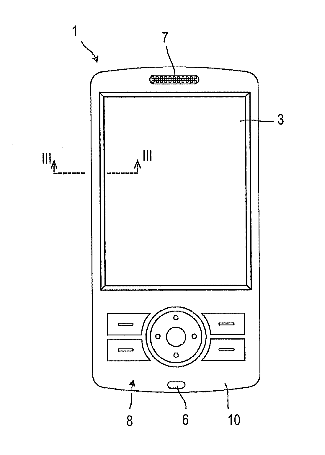
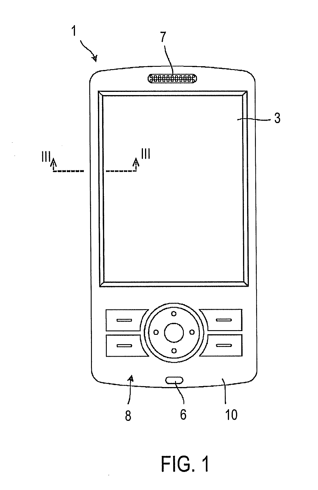
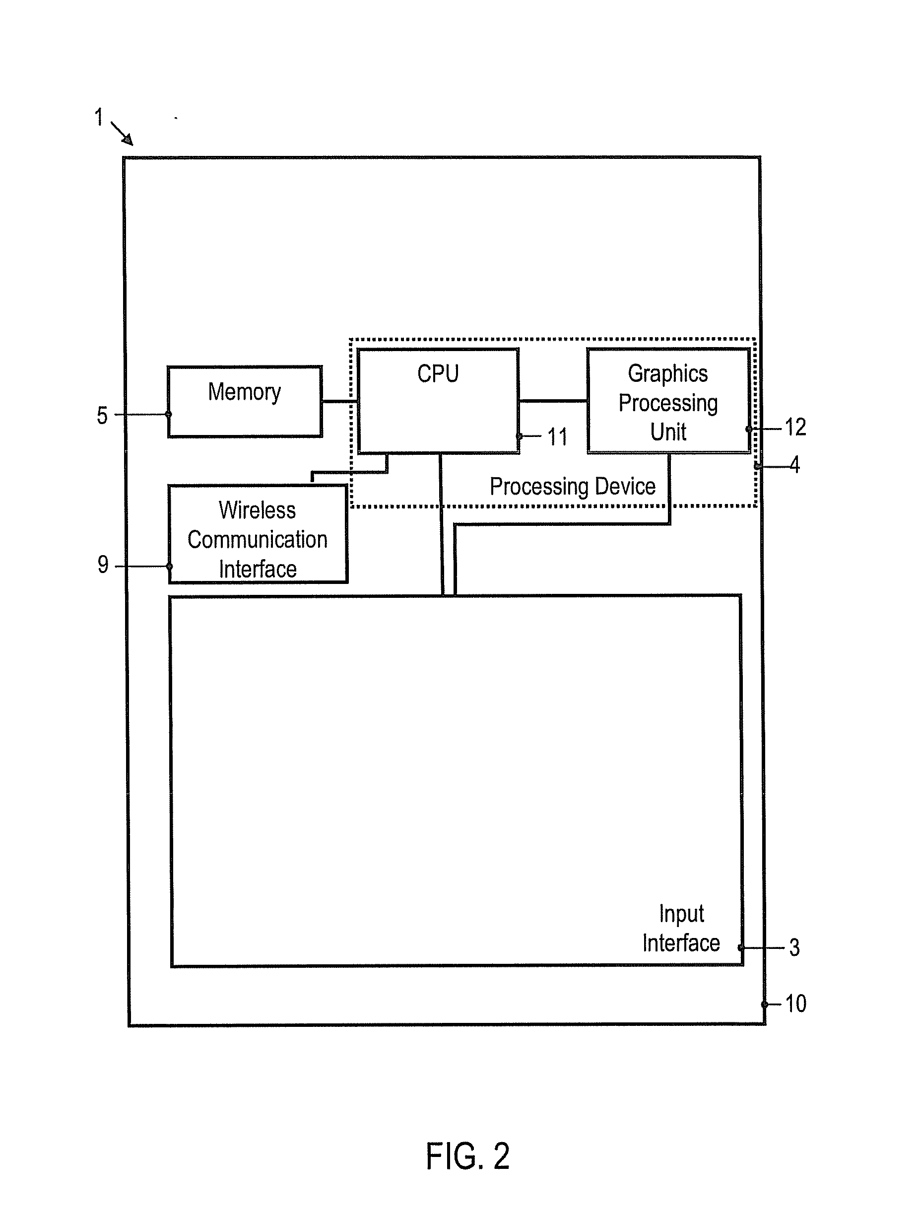
[0041]In the following, embodiments of the invention will be described in detail with reference to the accompanying drawings. It is to be understood that the following description of embodiments is not to be taken in a limiting sense. The scope of the invention is not intended to be limited by the embodiments described hereinafter or by the drawings, which are taken to be illustrative only.

[0042]The drawings are to be regarded as being schematic representations, and elements illustrated in the drawings are not necessarily shown to scale. Rather, the various elements are represented such that their function and general purpose become apparent to a person skilled in the art. Any connection or coupling between functional blocks, devices, components or other physical or functional units shown in the drawings or described herein may also be implemented by an indirect connection or coupling. A coupling between components may also be established over a wireless connection. Functional block...


PUM

PropertyMeasurementUnit
Forceaaaaaaaaaa
Flexibilityaaaaaaaaaa
Electrical conductoraaaaaaaaaa

Abstract

An input interface comprises a touch sensor panel having a surface and a first sensor arrangement provided on the surface to sense a position of a touch action with two-dimensional spatial resolution. A transparent window member is offset from the surface of the touch sensor panel in a direction perpendicular to the surface. A second sensor arrangement is interposed between the surface and the transparent window member. The second sensor arrangement is configured to sense a magnitude of a force normal to the surface applied by the touch action and pushing the window member toward the touch sensor panel.

Description

FIELD OF THE INVENTION[0001]The application relates to an input interface, a portable electronic device having an input interface, and a method of producing an input interface. The application relates in particular to input interfaces which include a touch panel sensor configured to sense a touch action with two-dimensional spatial resolution.BACKGROUND OF THE INVENTION[0002]Portable electronic devices provide functionalities which continue to be enhanced. With increasing processing capabilities and functionalities provided in the portable electronic device, it is increasingly challenging to provide input interfaces which allow the variety of functionalities to be controlled in an intuitive manner. Touch sensor panels which sense a touch action enhance the ways in which a user may interact with the portable electronic device. Touch sensor panels may be configured such that they provide information on the location at which a user touches a window. Touch sensor panels may be configure...

Claims


Application Information

Patent Timeline
IPC IPC(8): G06F3/0488
CPCG06F3/0488G06F3/0416Y10T29/49155G06F2203/04105G06F3/0414G06F3/044G06F3/04164G06F3/0446
Inventor BERG, PETERANTON, GEORGETA
Owner SONY MOBILE COMM INC
Learn More