System and method for increasing frequency tuning range

a technology of frequency tuning range and frequency tuning method, which is applied in the field of wireless communication, to achieve the effect of increasing the frequency tuning range of the rf/microwave lc oscillator, reducing the silicon footprint of the lc oscillator, and being easy to implemen

Active Publication Date: 2008-11-13
TEXAS INSTR INC
View PDF3 Cites 32 Cited by
  • Summary
  • Abstract
  • Description
  • Claims
  • Application Information

AI Technical Summary

Benefits of technology

[0010]An advantage of an embodiment is that the frequency tuning range of a RF / microwave LC oscillator is increased without the use of multiple oscillator cores and LC tanks. Since multiple oscillator cores and LC tanks are not used, the LC oscillator can be kept to a minimum size, thereby decreasing the silicon footprint of the LC oscillator.
[0011]A further advantage of an embodiment is that only an insignificant parasitic capacitance is added to the LC oscillator. Therefore, as the operating frequencies increase, there may not be a significant performance penalty. Furthermore, the embodiment may be easily implemented with very little additional cost in terms of design costs. Additionally, the embodiment requires very little additional space in an integrated circuit, thereby minimally impacting the overall cost of the oscillator.
[0012]Yet another advantage of an embodiment is that additional inductors can be added to the LC oscillator to provide a wide frequency tuning range. In other words, the embodiment may be combined with other techniques for increasing the LC oscillator's frequency tuning range. This may permit a further widening of the LC oscillator's frequency tuning range. For example, more than one inductor can be added to the LC oscillator and these added inductors can be switched in and out, either individually or in combination, to provide a wide frequency tuning range with potentially fine tuning adjustments.

Problems solved by technology

Unfortunately, in order to operate at different locations throughout the world, the world phone needs to be able to communicate with different cellular communications networks, each using a potentially different communications mechanism, as well as being able to tune its oscillator to different frequency ranges.

Method used


Image

  • System and method for increasing frequency tuning range
  • System and method for increasing frequency tuning range
  • System and method for increasing frequency tuning range

Examples


Embodiment Construction

[0026]The making and using of the embodiments are discussed in detail below. It should be appreciated, however, that the present invention provides many applicable inventive concepts that can be embodied in a wide variety of specific contexts. The specific embodiments discussed are merely illustrative of specific ways to make and use the invention, and do not limit the scope of the invention.

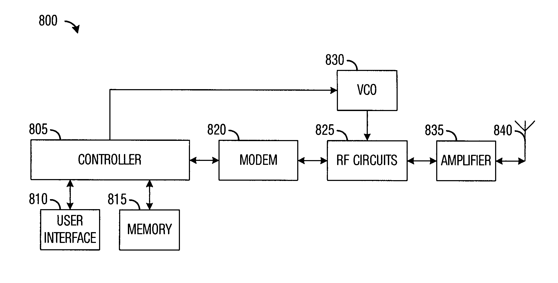
[0027]The embodiments will be described in a specific context, namely a multi-standard cellular telephone that needs to operate in multiple frequency ranges. The invention may also be applied, however, to other electronic devices, such as communications devices including transmitters and receivers, that have a need to operate in multiple frequency ranges.

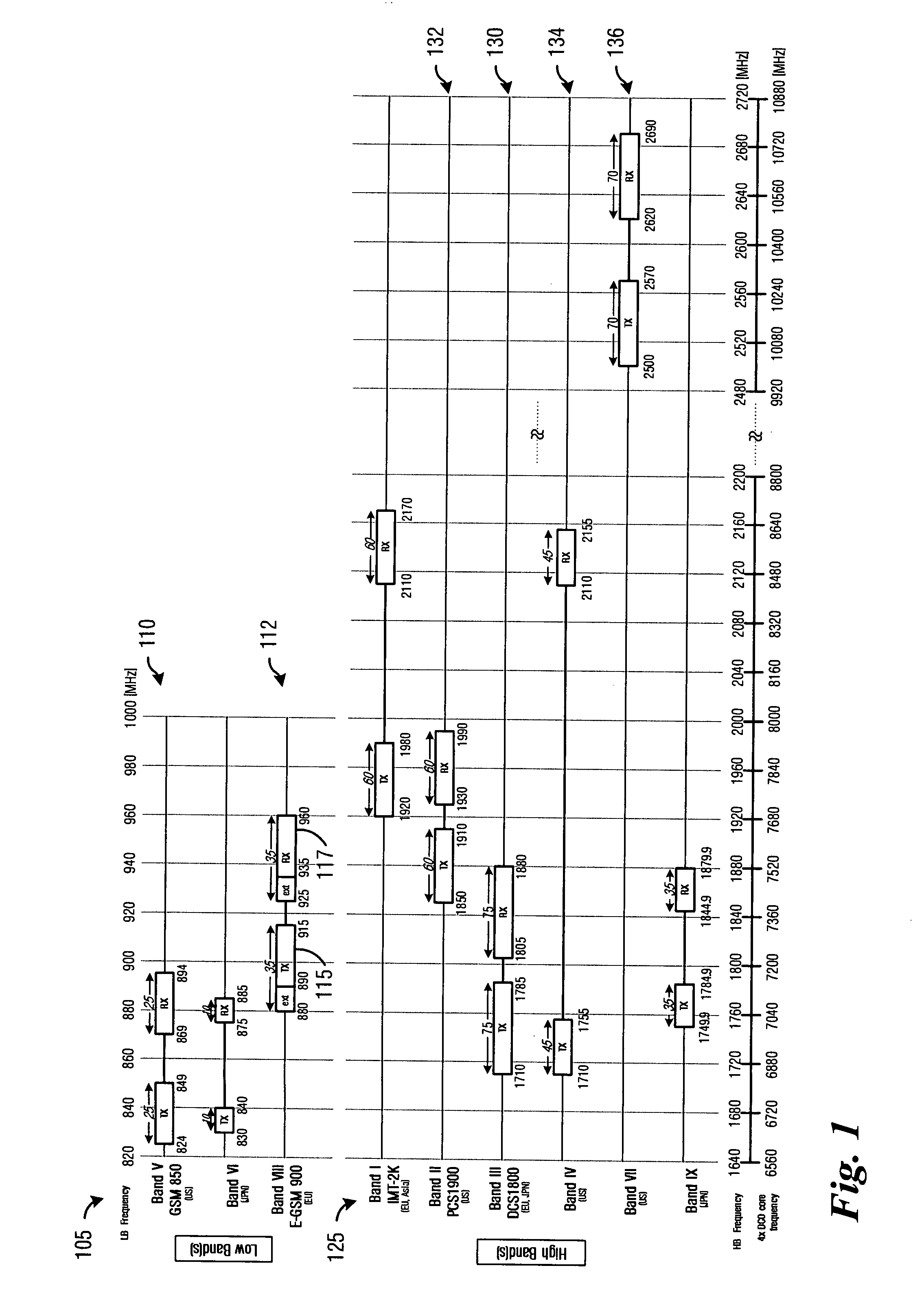
[0028]With reference now to FIG. 1, there is shown a frequency diagram for an exemplary cellular telephone, wherein the cellular telephone is a multi-standard telephone. The frequency diagram shown in FIG. 1 illustrates various frequency ranges ...


PUM


Abstract

System and method for increasing the frequency tuning range of a RF/microwave LC oscillator. An electronic communications device includes a controller to regulate the operation of the electronic communications device, a modem coupled to the controller, a radio frequency unit coupled to the controller and to the modem, an oscillator coupled to the controller and to the radio frequency unit, and an amplifier coupled to the radio frequency unit. The oscillator produces a timing and reference signal for the radio frequency unit based on control information from the controller. The oscillator includes a multi-tap inductor that may controllably alter its effective inductance to change the timing and reference signal provided to the radio frequency unit.

Description

TECHNICAL FIELD[0001]The present invention relates generally to a system and method for wireless communications, and more particularly to a system and method for increasing the frequency tuning range of a RF / microwave LC tank.BACKGROUND[0002]A desire of a cellular telephone user is to have a single cellular telephone that can operate anywhere in the world: a “world” phone. Unfortunately, in order to operate at different locations throughout the world, the world phone needs to be able to communicate with different cellular communications networks, each using a potentially different communications mechanism, as well as being able to tune its oscillator to different frequency ranges. This is due to the wide variety of communications standards and frequency bands being used in different areas of the world. For example, in the United States, it is common to encounter GSM (Global System for Mobile Communications), CDMA (Code Division Multiple Access), TDMA (Time-Division Multiple Access),...

Claims


Application Information

Patent Timeline
Patent Type & Authority Applications(United States)
IPC IPC(8): H03B7/14G06F17/50H04M1/00
CPCG06F17/5063H03B2201/0216H03B5/1228H03B5/1231H03B5/1296H03B5/1268H03B5/1215H03B5/1265H03B5/124H03B5/1225G06F30/36
Inventor HUNG, CHIH-MINGBARTON, NATHEN
Owner TEXAS INSTR INC
Why Eureka
Try Eureka