

Automated cancellation of harmonics using feed forward filter reflection for radar transmitter linearization
a technology of linearization and filter reflection, applied in the field of radar, can solve the problems of not being able to achieve the effect of reducing the loss through the filter, and reducing the cost of the system
- Summary
- Abstract
- Description
- Claims
- Application Information
AI Technical Summary
Benefits of technology
Problems solved by technology
Method used
Image

Examples
Embodiment Construction
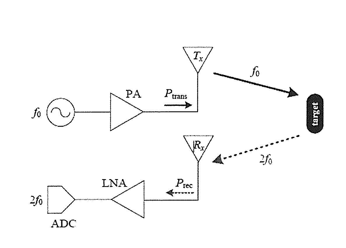
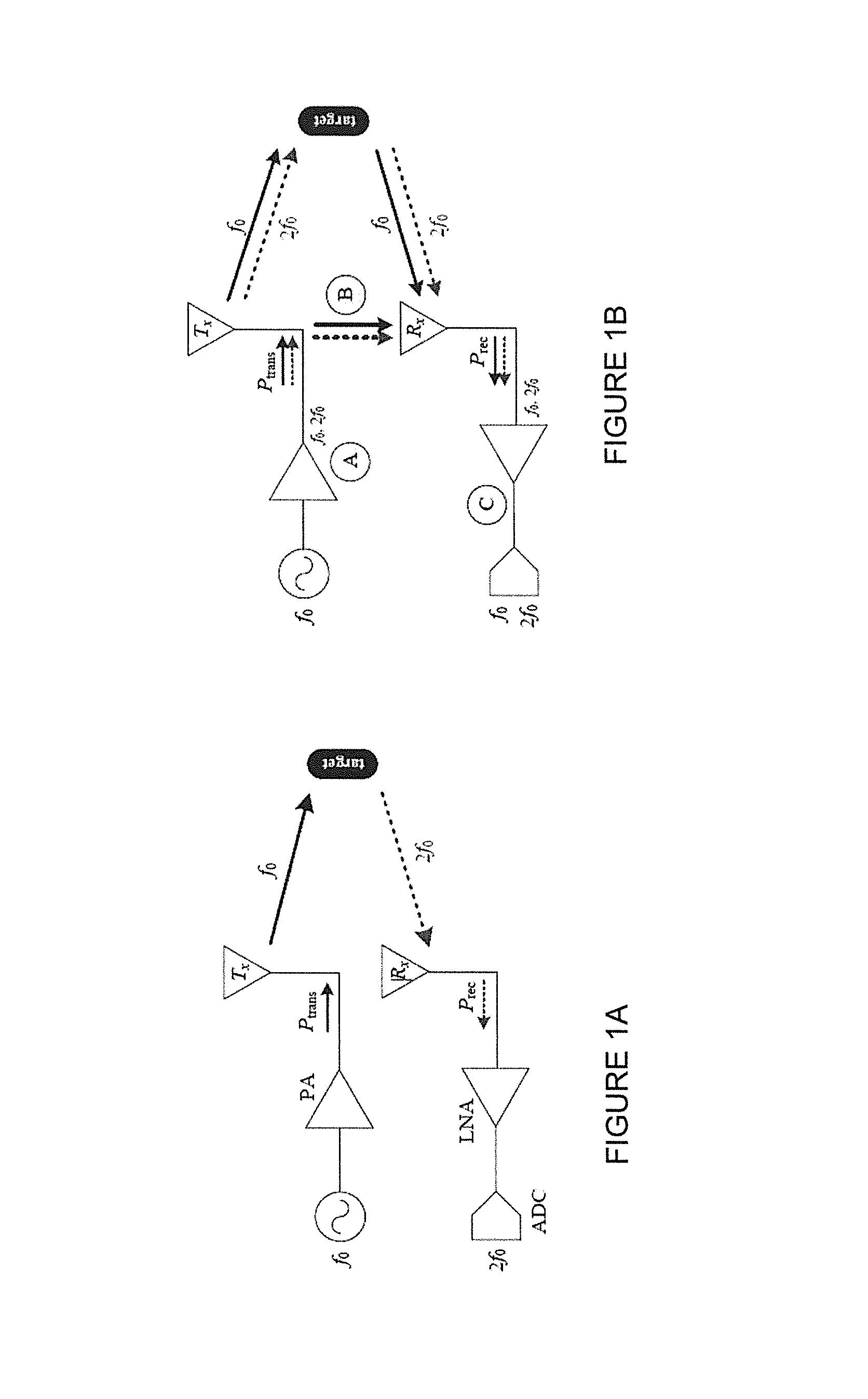
[0040]This invention resides in a system and methods for automatic linearizing a harmonic radar transmitter. In the preferred embodiments, a transmitter for a harmonic radar transmits f0 and receives only 2f0. The solution involves a form of tunable lowpass filter whose passband remains unaltered by tuning but whose deepest stopband rejection (notch) frequency is flexible. The notch frequency corresponds to the harmonic to be received from the target. For this study, the notch is tuned to 2f0, but it may also be tuned to a higher harmonic (e.g. 3f0, 4f0, etc.) whose reception is used for target classification.
[0041]Tuning occurs in a low-power branch parallel to the lowpass-filtered signal, which: minimizes signal loss, enables fast, electronic tuning, maintains linearity in the high-power branch. This invention demonstrates the feasibility of electronically tuning such a system.
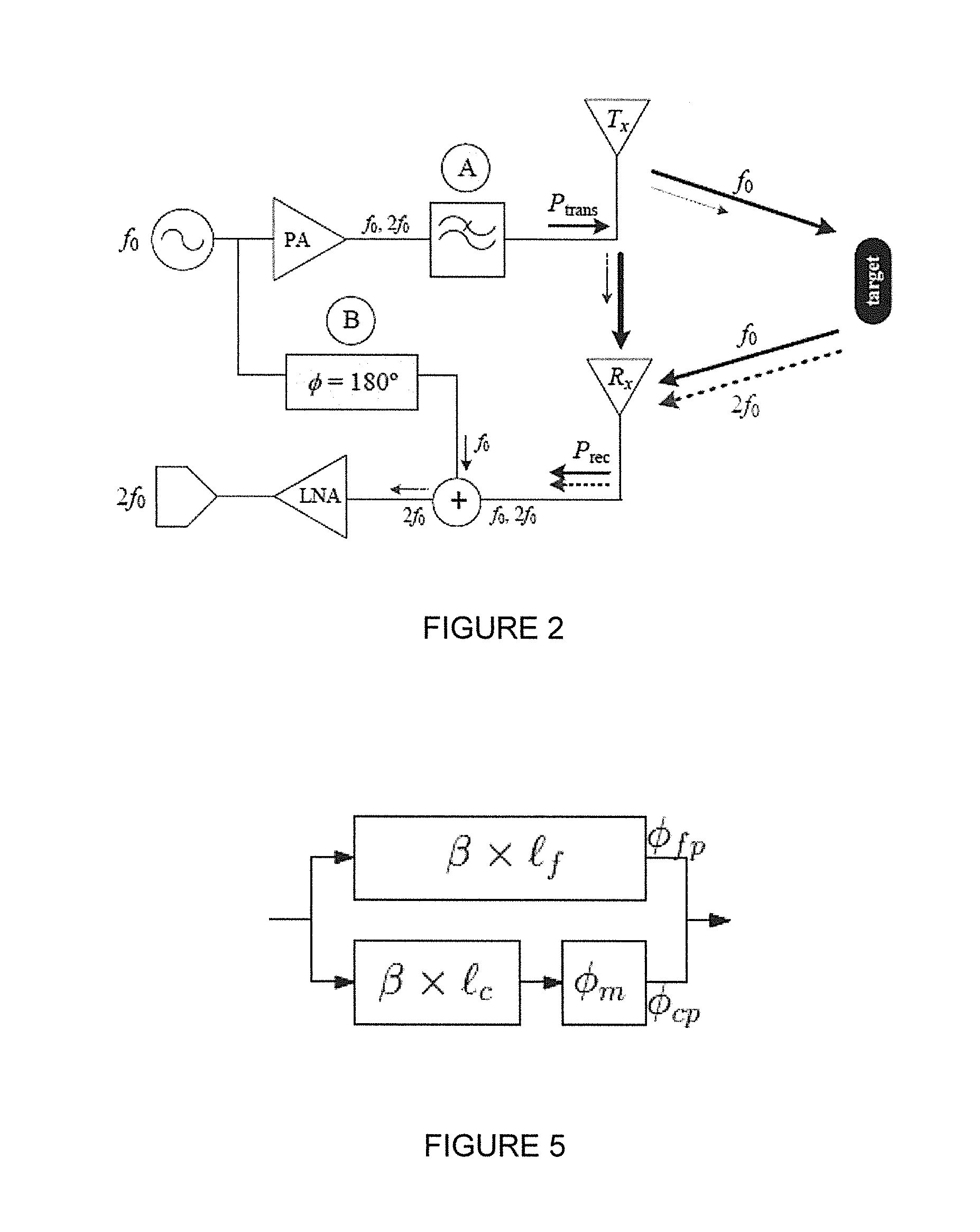
Feed-Forward Filter Reflection (FFFR)
[0042]A novel linearization methodology for harmonic radar is presen...
PUM
 Abstract
Description
Claims
Application Information