Recirculation fan and fan assembly thereof

a technology of recirculation fan and fan assembly, which is applied in the direction of liquid fuel engine, machine/engine, combination engine, etc., can solve the problems of space utilization decline, and achieve the effect of deteriorating space utilization and increasing airflow

Inactive Publication Date: 2013-06-13
DELTA ELECTRONICS INC
View PDF5 Cites 3 Cited by
  • Summary
  • Abstract
  • Description
  • Claims
  • Application Information

AI Technical Summary

Benefits of technology

[0005]As previously described, if the amount of the airflow required for indoor convection is increased, the conventional fan should have a longer and larger fan blade and a large-power and large-size motor is necessary. Under this circumstance, the regions unable to inhale or exhale the airflow will be increased, and the space utilization is deteriorated. One object of the present invention is to provide a recirculation fan and a fan assembly of the recirculation fan for eliminating the drawbacks encountered from the prior art.

Problems solved by technology

Under this circumstance, the regions unable to inhale or exhale the airflow will be increased, and the space utilization is deteriorated.

Method used


Image

  • Recirculation fan and fan assembly thereof
  • Recirculation fan and fan assembly thereof
  • Recirculation fan and fan assembly thereof

Examples


Embodiment Construction

[0016]The present invention will now be described more specifically with reference to the following embodiments. It is to be noted that the following descriptions of preferred embodiments of this invention are presented herein for purpose of illustration and description only. It is not intended to be exhaustive or to be limited to the precise form disclosed.

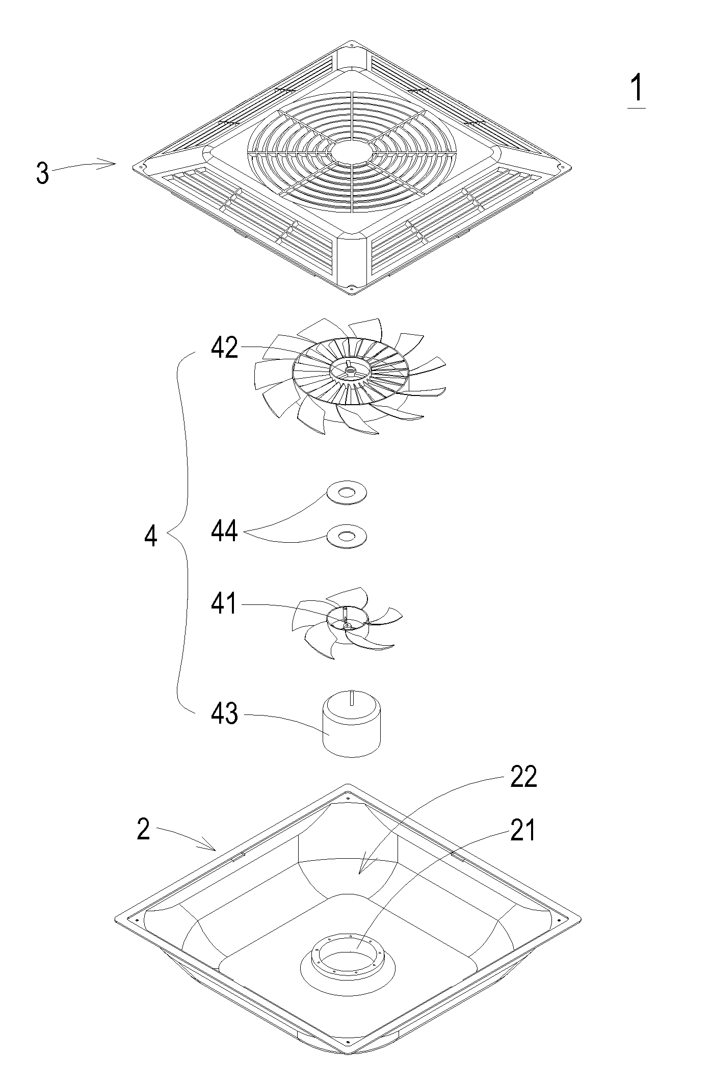
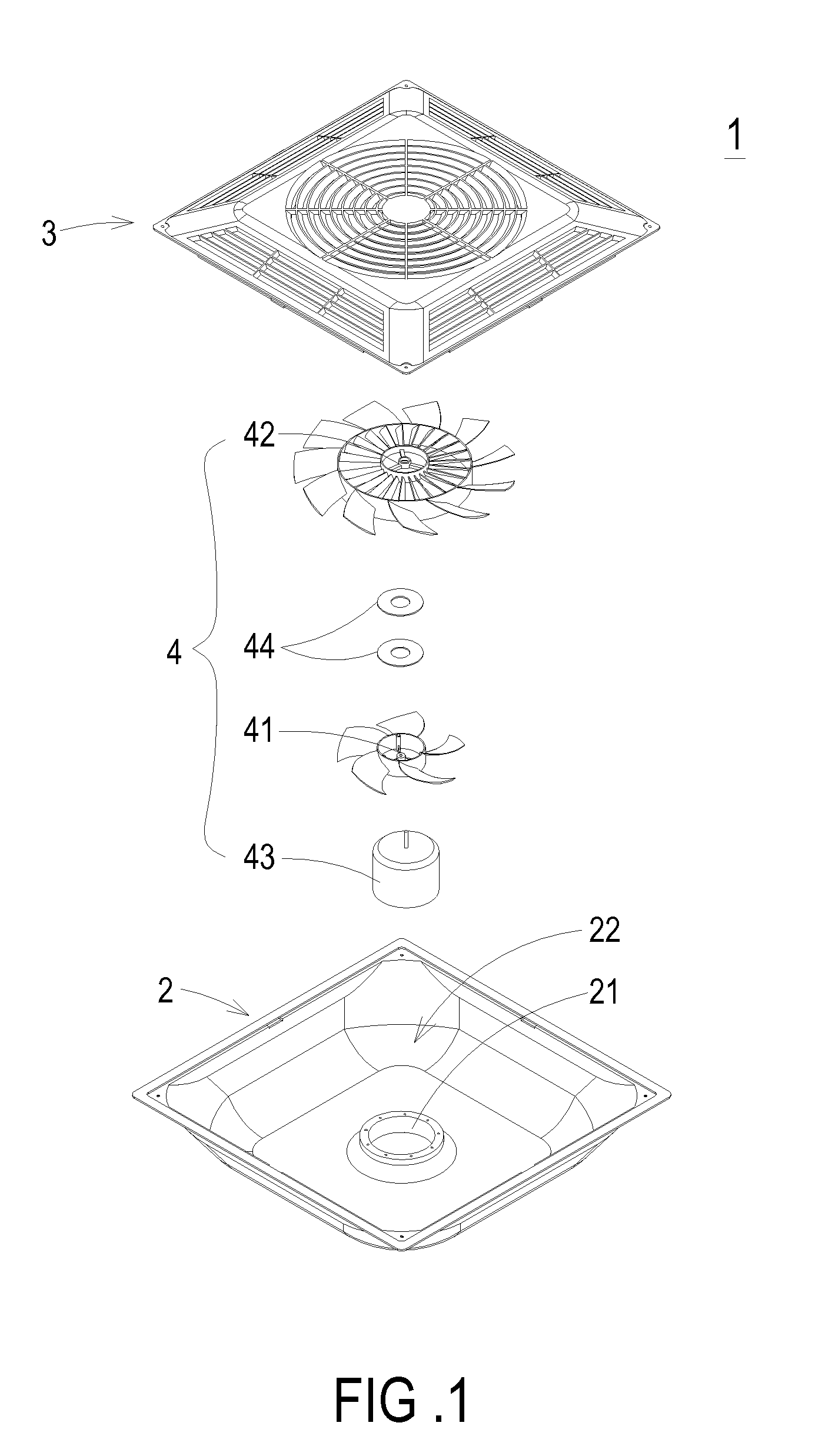
[0017]FIG. 1 is a schematic exploded view illustrating a recirculation fan according to an embodiment of the present invention. The recirculation fan 1 is used to increase the convection and control the environmental temperature. As shown in FIG. 1, the recirculation fan 1 comprises a casing 2, a covering member 3, and a fan assembly 4. The casing 2 has a base 21. The base 21 has a cylindrical, cubic or rectangular space. The base 21 is integrally formed with the casing 2. Alternatively, the base 21 may be fixed on the casing 2 by an adhering means, a screwing means or an engaging means. After the covering member 3 is combined wi...


PUM


Abstract

A recirculation fan includes a casing, a covering member, and a fan assembly. The casing has a base. The covering member is coupled with the casing to define an accommodation space. The fan assembly is disposed within the accommodation space, and includes a first impeller, a second impeller, a motor, and a plurality of magnetic elements. The second impeller is located beside the first impeller. The motor is fixed on the base of the casing and connected with the first impeller for driving rotation of the first impeller. The magnetic elements are arranged between the first impeller and the second impeller. A wind force generated by the first impeller and a magnetic torque resulted from a magnetic vortex of the magnetic elements cause contactless rotation of the second impeller.

Description

FIELD OF THE INVENTION[0001]The present invention relates to a recirculation fan, and more particularly to a recirculation fan driven by a composite motive force. The present invention also provides a fan assembly of the recirculation fan.BACKGROUND OF THE INVENTION[0002]In recent years, with increasing environmental consciousness, more and more products are designed in views of energy conservation and carbon reduction policy. Consequently, government organizations, enterprises, schools or families pay much attention to the reduction of the frequency and time period of using the air conditioners. For maintaining air circulation and increasing space utilization, a variety of new fans and recirculation fans are introduced into the market.[0003]For most fans, a motor is employed to drive rotation of the fan blades and produce airflow. Consequently, the convection within the indoor construction site will be enhanced and the indoor temperature can be controlled. The mainstream of the ind...

Claims


Application Information

Patent Timeline
Patent Type & Authority Applications(United States)
IPC IPC(8): F04D29/32F04D19/00
CPCF04D25/082F04D29/541F04D25/12F04D19/002F04D25/026F04D25/024F04D25/166F04D25/022F04D19/026
Inventor CHANG, SHUN-CHENLIU, WEN-BIN
Owner DELTA ELECTRONICS INC
Why Eureka
Try Eureka