

Surgical treatment system
a treatment system and surgical technology, applied in the field of surgical treatment systems, can solve the problems of increasing the cost, reducing the size of the heating treatment section, and reducing the number of connections to the heating elements,
- Summary
- Abstract
- Description
- Claims
- Application Information
AI Technical Summary
Benefits of technology
Problems solved by technology
Method used
Image

Examples
first embodiment
[0039]A first embodiment will be described with reference to FIG. 1, FIG. 2, FIG. 3, FIG. 4, FIG. 5A, FIG. 5B, FIG. 6A, FIG. 6B, and FIG. 7.
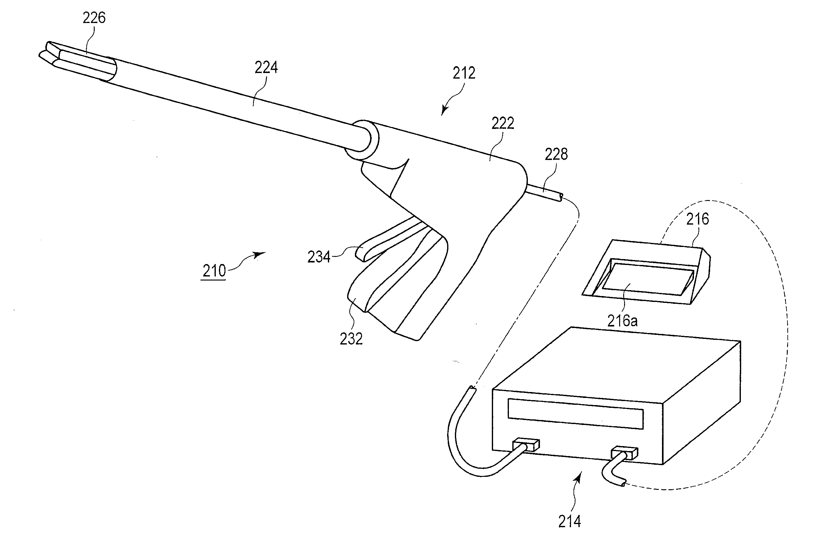
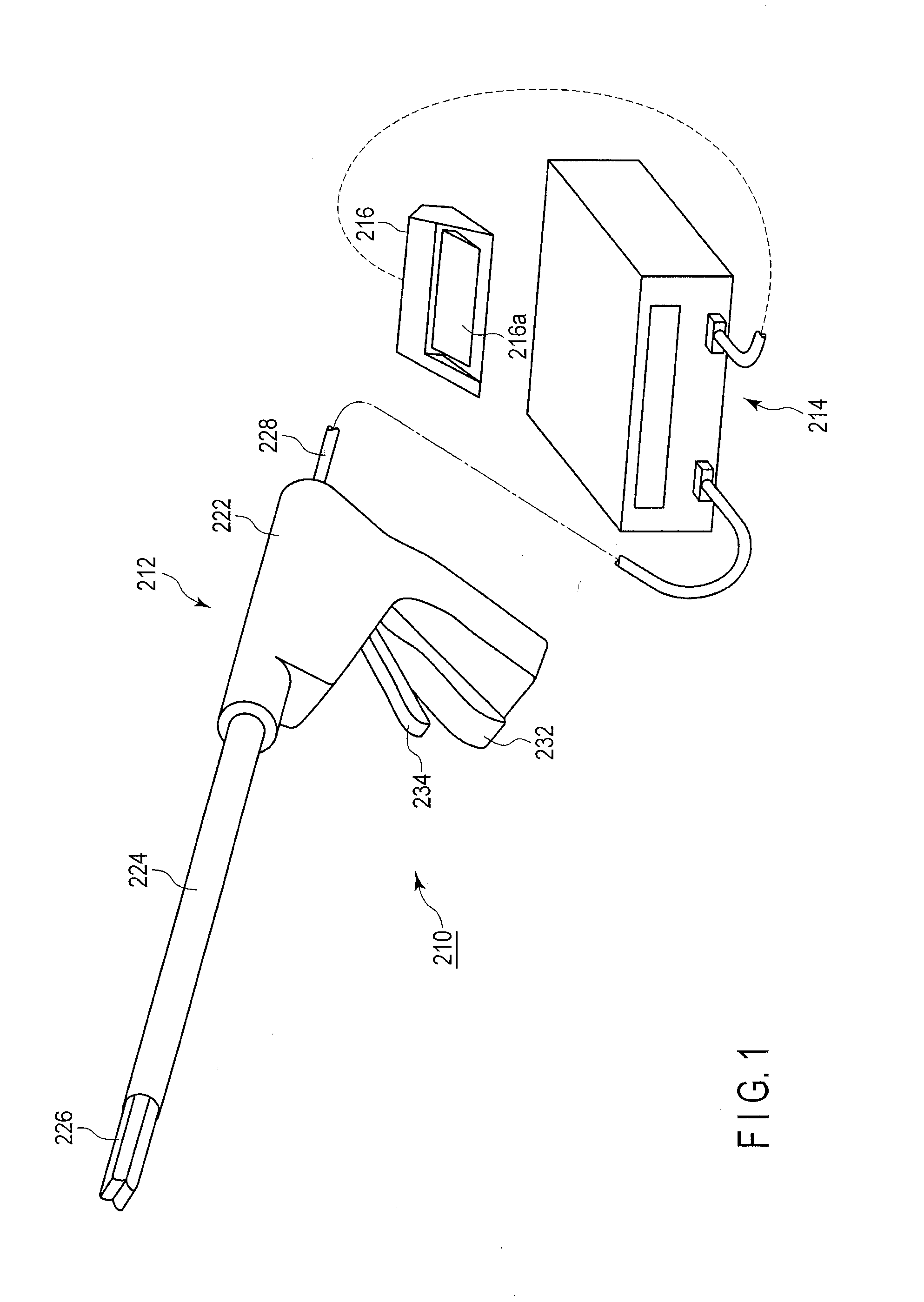
[0040]As shown in FIG. 1, a surgical treatment system 210 comprises an energy treatment instrument 212, an energy source 214, and a foot switch 216. The surgical treatment system 210 allows energy generated by the energy source 214 to act on living tissue via the energy treatment instrument 212 to treat the living tissue.
[0041]The energy treatment instrument 212 is a surgical instrument which treats living tissue using high-frequency energy and thermal energy. The energy treatment instrument 212 is a surgical treatment instrument of a linear type which carries out treatment, for example, through the abdominal wall.
[0042]The energy treatment instrument 212 comprises a handle 222, a shaft 224, and a holding section 226 which is an openable and closable heating treatment section holding the living tissue to carry out a treatment such as a coagulati...
third embodiment
[0137]Now, a third embodiment according to the present invention will be described with reference to FIG. 10, FIG. 11A, FIG. 11B, and FIG. 11C. The same components of the third embodiment as the corresponding components of the first and second embodiments are denoted by the same reference numerals as those in the first and second embodiments. Description of these components is omitted.
[0138]As shown in FIG. 10, the first high-frequency electrode 266 comprises a zone A on the leading end 266c side, a zone B disposed between the leading end 266c side and the base end 266d side, and a zone C on the base end 266d side. The first high-frequency electrode 266 controls the group of heater members 300 on the leading end 266c side of the first high-frequency electrode 266 (zone A), the group of heater members 230 between the leading end 266c side and base end 266d side of the first high-frequency electrode 266 (zone B), and the group of heater members on the base end 266d side of the first h...
second embodiment
[0169]Thus, like the second embodiment, the present embodiment can control, even with increased number of zones, the heater members 300 in each zone independently of the heater members 300 in the other zones and thus carry out the treatment of the living tissue in each zone independently of the treatment of the living tissue in the other zones. The control for each zone according to the present embodiment may be performed based on the amount by which the pedal 216a of the foot switch 216 is depressed or using the switch (not shown in the drawings) disposed in the energy source 214.
[0170]Furthermore, the present embodiment provides a wiring path between the heater member energization line 2681a and the heater member energization line 2681b on which path the resistance patters 307 on the heater member 301a and heater member 301b arranged in zone A are connected together in series along the substantial U shape of the first high-frequency electrode 266. Additionally, in this case, the p...
PUM
 Abstract
Description
Claims
Application Information