Hybrid traffic system and associated method

a traffic system and hybrid technology, applied in the field of traffic sensor systems, can solve the problems of undesired false alarms of machine vision sensors, undesirable increase of false alarms and early detector actuation, and the effect of applying shadow false alarm filters to machine vision systems

Active Publication Date: 2013-06-13
IMAGE SENSING SYSTEMS
View PDF15 Cites 113 Cited by
  • Summary
  • Abstract
  • Description
  • Claims
  • Application Information

AI Technical Summary

Problems solved by technology

Shadow can cause false alarms with machine vision sensors.
Also, applying shadow false alarm filters to machine vision systems can have an undesired side effect of causing missed detections of dark objects.
However, headlight splash often causes an undesirable increase in false alarms and early detector actuations.
Machine vision may be susceptible to occlusion false alarms, and may have problems with occlusions falsely turning on detectors in adjacent lanes.
Like machine vision, though, radar will likely miss vehicles that are fully or near fully occluded.
Machine vision detectors occasionally lose the ability to detect vehicles in low-contrast conditions.
Machine vision systems can have the ability to detect low contrast conditions and force detectors into a failsafe always-on state, though this presents traffic flow inefficiency at an intersection.
The only exception for radar low contrast performance is heavy rain or snow, and especially snow buildup on a radome of the radar; the radar may miss objects in those conditions.
Sensor failure generally refers to a complete dropout of the ability to detect for a machine vision, radar or any other sensing modality.
It can also encompass partial sensor failure.
A sensor failure condition may occur due to user error, power outage, wiring failure, component failure, interference, software hang-up, physical obstruction of the sensor, or other causes.
In many cases, the sensor affected by sensor failure can self-diagnose its own failure and provide an error flag.
In other cases, the sensor may appear to be running normally, but produce no reasonable detections.
There are an increased number of sources of shadows, headlight splash, or occlusions in high traffic density conditions, which could potentially increase false alarms.
However, there is also less practical opportunity for false alarms during high traffic density conditions because detectors are more likely to be occupied by a real object (e.g., vehicle).
Radar generally experiences reduced performance in heavy traffic, and is more likely to miss objects in heavy traffic conditions.
Machine vision usually cannot reliably measure vehicle distances or speeds in the far-field, though certain types of false alarms actually become less of a problem in the far-field because the viewing angle becomes nearly parallel to the roadway, limiting visibility of optical effects on the roadway.
For example, a radar may experience poor positive detection rates at distances significantly below a rated maximum vehicle detection range.
Radar is usually not capable of detecting slow-moving or stopped objects (below approximately 4 km / hr or 2.5 ml / hr).
Missing stopped objects is less than optimal, as it could lead an associated traffic controller 86 to delay switching traffic lights to service a roadway approach 38, delaying or stranding drivers.
Machine vision sensor movement can cause misalignment of vision sensors with respect to established (i.e., fixed) detection zones, creating a potential for both false alarms and missed detections.
Radar may experience errors in its position estimates of objects when the radar is moved from its original position.
This could cause both false alarms and missed detections.
If vehicle tracks don't consistently align with the lanes, then it is likely a sensor's position has been disturbed.
Vehicle classification is difficult during nighttime and poor weather conditions because machine vision may have difficulty detecting vehicle features; however, radar is unaffected by most of these conditions and thus can generally improve upon basic classification accuracy during such conditions despite known limitations of radar at measuring vehicle length.
For wrong way objects (e.g., vehicles), the radar can easily determine if an object is traveling the wrong way (i.e., in the wrong direction on a one-way roadway) via Doppler radar, with a small probability of false alarm.

Method used


Image

  • Hybrid traffic system and associated method
  • Hybrid traffic system and associated method
  • Hybrid traffic system and associated method

Examples


Embodiment Construction

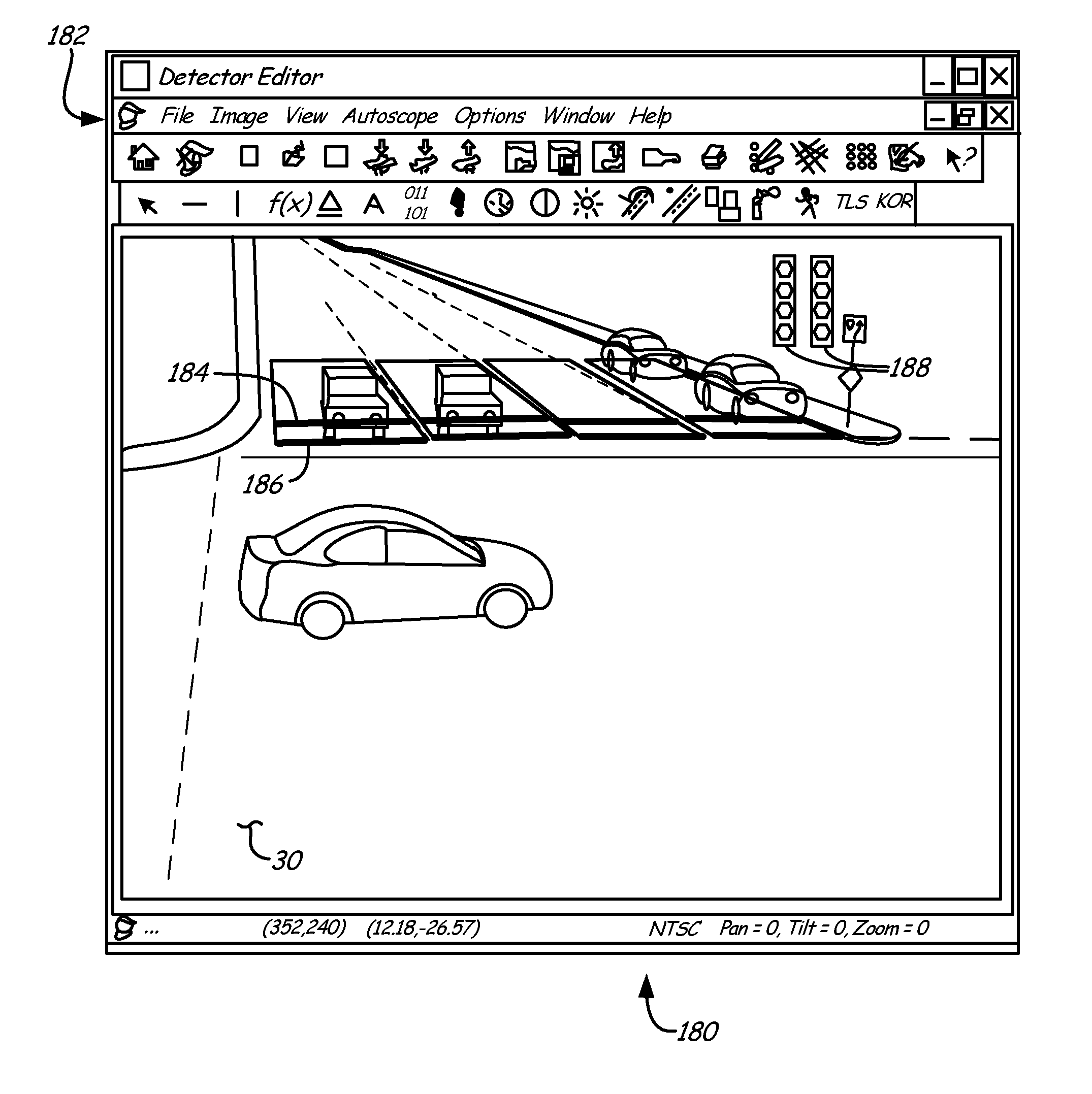
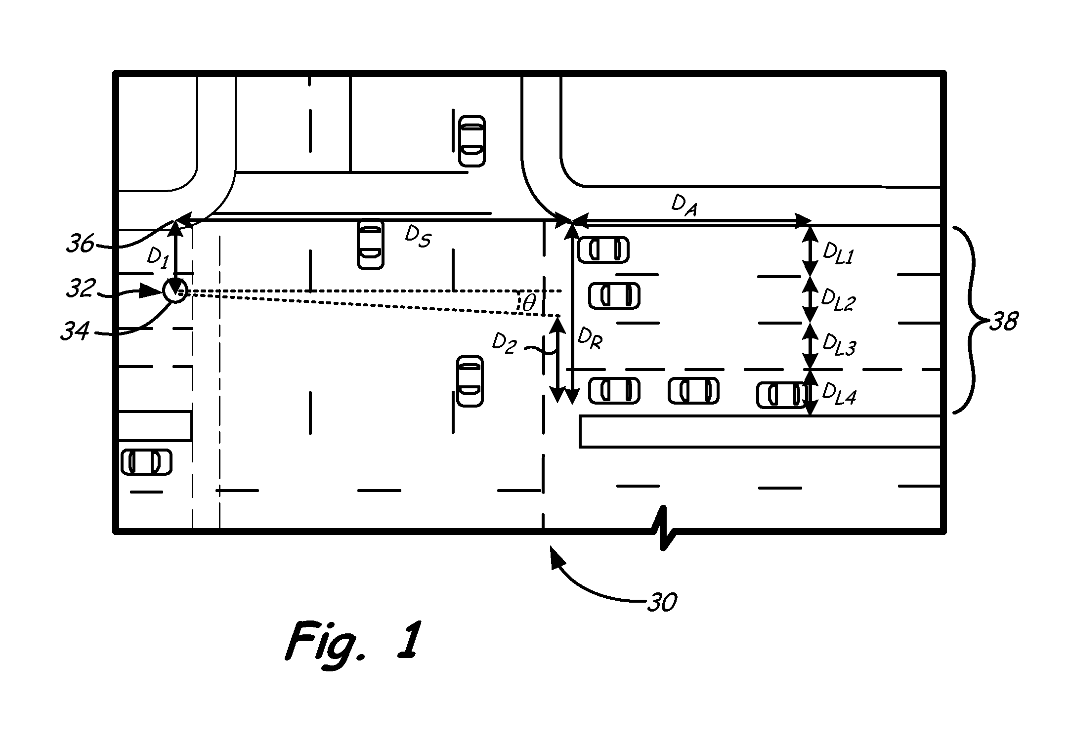
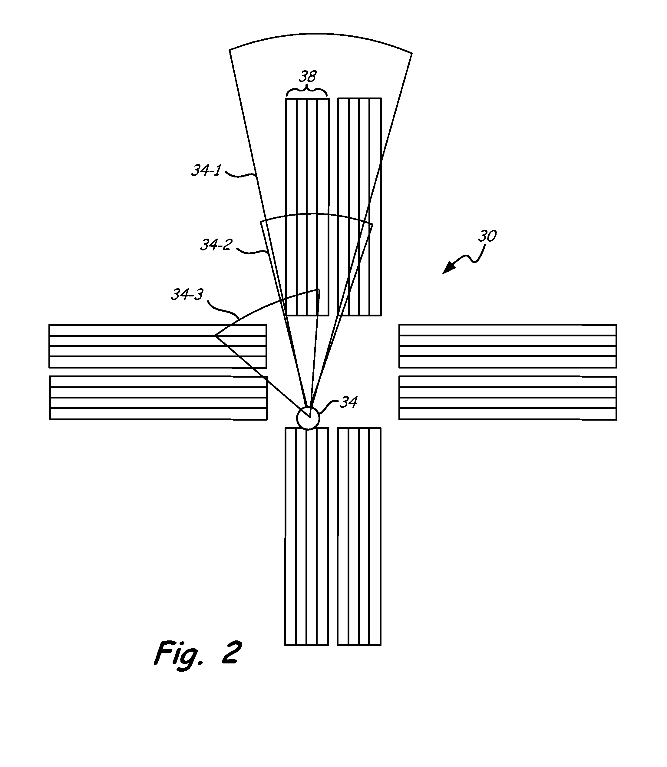
[0030]In general, the present invention provides a traffic sensing system that includes multiple sensing modalities, as well as an associated method for normalizing overlapping sensor fields of view and operating the traffic sensing system. The system can be installed at a roadway, such as at a roadway intersection, and can work in conjunction with traffic control systems. Traffic sensing systems can incorporate radar sensors, machine vision sensors, etc. The present invention provides a hybrid sensing system that includes different types of sensing modalities (i.e., different sensor types) with at least partially overlapping fields of view that can each be selectively used for traffic sensing under particular circumstances. These different sensing modalities can be switched as a function of operating conditions. For instance, machine vision sensing can be used during clear daytime conditions and radar sensing can be used instead during nighttime conditions. In various embodiments, ...


PUM


Abstract

A traffic sensing system for sensing traffic at a roadway includes a first sensor having a first field of view, a second sensor having a second field of view, and a controller. The first and second fields of view at least partially overlap in a common field of view over a portion of the roadway, and the first sensor and the second sensor provide different sensing modalities. The controller is configured to select a sensor data stream for at least a portion of the common field of view from the first and / or second sensor as a function of operating conditions at the roadway.

Description

BACKGROUND[0001]The present invention relates generally to traffic sensor systems and to methods of configuring and operating traffic sensor systems.[0002]It is frequently desirable to monitor traffic on roadways and to enable intelligent transportation system controls. For instance, traffic monitoring allows for enhanced control of traffic signals, speed sensing, detection of incidents (e.g., vehicular accidents) and congestion, collection of vehicle count data, flow monitoring, and numerous other objectives.[0003]Existing traffic detection systems are available in various forms, utilizing a variety of different sensors to gather traffic data. Inductive loop systems are known that utilize a sensor installed under pavement within a given roadway. However, those inductive loop sensors are relatively expensive to install, replace and repair because of the associated road work required to access sensors located under pavement, not to mention lane closures and traffic disruptions associ...

Claims


Application Information

Patent Timeline
Patent Type & Authority Applications(United States)
IPC IPC(8): G08G1/00
CPCG08G1/00G08G1/0116
Inventor AUBREY, KENGOVINDARAJAN, KIRANBRUDEVOLD, BRYANANDERSON, CRAIGSTEINGRIMSSON, BALDUR
Owner IMAGE SENSING SYSTEMS
Why Eureka
Try Eureka