
System and method for compensating orientation of a portable device

a portable device and orientation technology, applied in the direction of speed measurement using gyroscopic effects, instruments, surveying and navigation, etc., can solve the problems of slowing or dropping the performance of the processing unit, unable to fully exploit the advantages of the technique, and affecting the immediacy of interaction with the user

Inactive Publication Date: 2013-06-13
STMICROELECTRONICS SRL
View PDF8 Cites 25 Cited by
  • Summary
  • Abstract
  • Description
  • Claims
  • Application Information

AI Technical Summary

Benefits of technology

This patent is about a system and method for making sure that a mobile device is always facing the right way.

Problems solved by technology

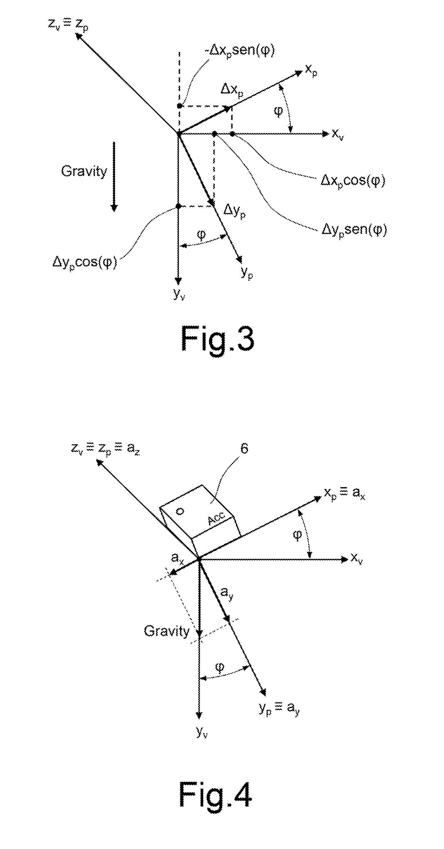
In general, the problem inherent in these applications thus includes transforming the path described by an object free to move in a three-dimensional space (the portable device) into displacements to be carried out in a fixed reference system (that of the display screen).
Even though it enables, at least theoretically, the problem of roll compensation to be overcome, the technique described has, however, certain limitations that do not enable complete exploitation of its advantages.
(10), (11) and (12) it is evident that the determination of the roll rotation angle φ entails execution of mathematical and trigonometric functions that are relatively burdensome from the computational standpoint (a square root, an arctangent, a sine and a cosine), which can cause slowing or drops in performance of the processing unit that governs general operation of the system (determining, for example, slower displacements of the cursor on the display screen 2, thus jeopardizing the immediacy of interaction with the user).
(10) and (11), with respect to the values assumed dynamically by the roll rotation angle φ of the portable device 1, it is evident that movement artifacts arise whenever errors are committed in the estimation of the same roll rotation angle φ.
However, the present Applicant has verified that this solution is not free from drawbacks, in particular on account of the delay introduced by the lowpass filter for extracting just the d.c. component of the signal, which generates a “wake” effect on the display screen, as a result of the application of Eqs.
A better performance in terms of phase delay can be obtained by shifting the cutoff frequency of the filter up a few hertz, but this does not enable components of acceleration at low frequency to be adequately suppressed (for example, dynamic and centrifugal accelerations that derive from rotational movements repeated in time, as discussed hereinafter).
Basically, the present Applicant has verified a solution that envisages the use of an accelerometer sensor, possibly also combined with an appropriate filtering of the signals, may not prove sufficient in a wide range of operating conditions, to provide an adequate compensation of the movement artifacts due to roll rotations of the portable device 1.
Given the frequency characteristics, these dynamic components of acceleration are difficult to suppress by the filtering techniques that may be commonly used because they are very close to the DC component.
A low-pass filter drawback can be experienced in case of constant velocity rotation.

Method used


Image

  • System and method for compensating orientation of a portable device
  • System and method for compensating orientation of a portable device
  • System and method for compensating orientation of a portable device

Examples


Embodiment Construction

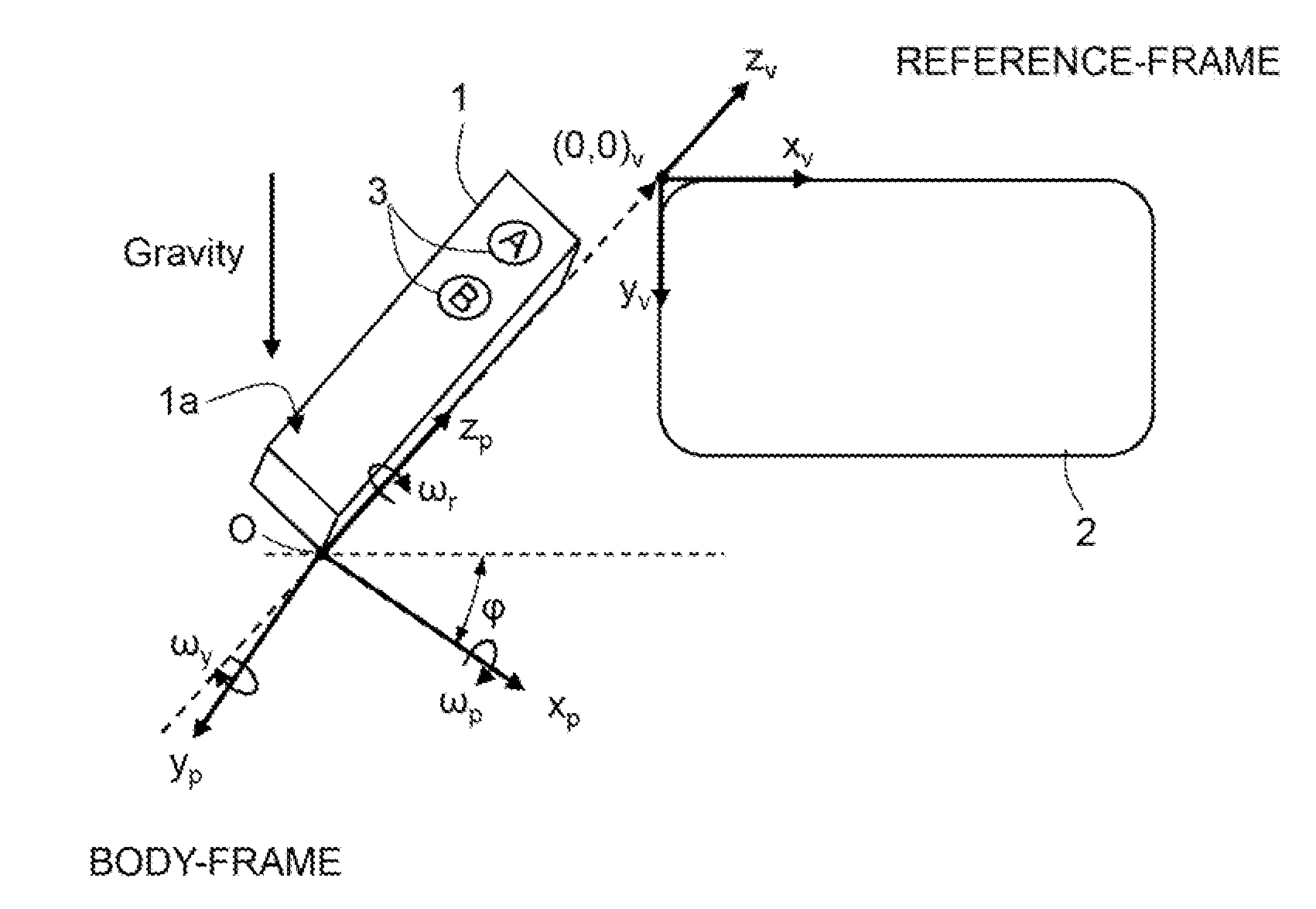
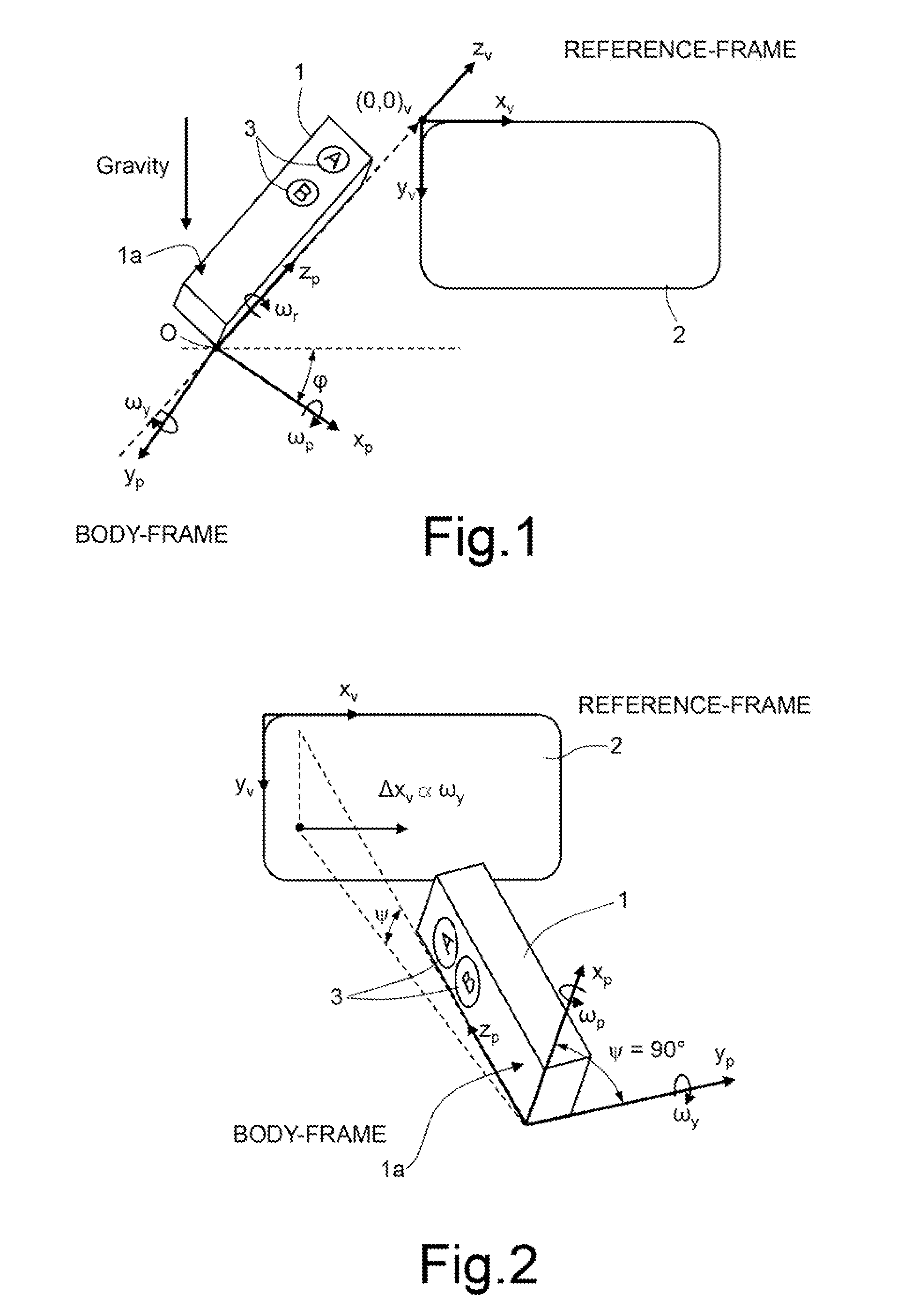
[0060]As will be described in detail in what follows, an aspect of the present disclosure envisages, in order to compensate the orientation of the portable device, use of a gyroscopic sensor for determining the roll angular velocity to which the portable device is subjected, and the integration of the roll angular velocity for deriving the roll rotation angle to be used for the compensation operations. These compensation operations may be made in a way similar to what has been described previously with reference to Eqs. (10) and (11), i.e., by using the rotation matrix associated to the roll rotation angle.

[0061]As illustrated in FIG. 8 (in general, in this figure and in the subsequent ones, elements that are similar to others already described previously are designated by the same reference numbers), the roll rotation angle, once again designated by φ, is hence derived as a function of the roll rotation velocity ωr of the portable device 1 about the longitudinal axis zp, obtained f...


PUM


Abstract

A system for compensating orientation of a portable device is provided with a processing unit for: determining a roll rotation angle of the portable device in a mobile reference system associated thereto; and applying a rotation matrix, which is a function of the roll rotation angle, for transforming relative displacements of the mobile device in the mobile reference system into corresponding displacements in a fixed reference system, of an inertial type, thus compensating the orientation of the portable device. The processing unit determines the roll rotation angle, in the presence of dynamic acceleration, by means of: acquisition of a roll angular velocity of the portable device by a gyroscopic sensor fixed with respect thereto; and time integration of the same roll angular velocity.

Description

BACKGROUND[0001]1. Technical Field[0002]The present disclosure relates to a system and a method for compensating orientation of a portable device (handheld device), such as for pointing applications or the like, in which it is desired to establish a correspondence between movements of the portable device, imparted by a user, and commands to be executed with respect to a fixed reference system (for example, for implementing displacements of a cursor, or similar element, on a screen, or similar element for displaying or representation of information).[0003]2. Description of the Related Art[0004]As is known, there are several applications in which a portable (or handheld) device is used by a user to interact with a user interface of an electronic apparatus, wherein displacements imparted to the portable device by the user are converted into commands for the electronic apparatus by the interface, for example for governing displacements of a cursor or of other images represented on a dis...

Claims


Application Information

Patent Timeline
IPC IPC(8): G01B7/30
CPCG06F3/0346G01B7/30
Inventor MARINONI, ALBERTO
Owner STMICROELECTRONICS SRL
Learn More