Swimming Pool Cleaner

a technology for cleaning pools and pool pipes, applied in gymnasiums, construction, buildings, etc., can solve the problems of large debris clogging pool pipes, limitation is the opposite of the suction cleaning method, and the size of the suction pool cleaner is also limited

Active Publication Date: 2013-06-20
HAYWARD IND INC
View PDF29 Cites 38 Cited by
  • Summary
  • Abstract
  • Description
  • Claims
  • Application Information

AI Technical Summary

Benefits of technology

[0012]This invention is an improved swimming pool cleaner of the type movable along an underwater pool surface to clean debris therefrom. The swimming pool cleaner of the present invention provides an important advantage of substantially strain-free and tool-free assembly.

Problems solved by technology

Suction swimming pool cleaners are also limited to the debris size due to loss of suction if the inlet and / or outlet orifices are widened to accommodate such large debris and the possibility of large debris clogging the pool pipes.
With a pressure swimming pool cleaner, the limitation is the opposite to the suction cleaner.
The problem is that most often only one cleaner is used in a pool.
However, just few years later, when trees and bushes have grown up, the debris becomes overwhelming and constantly plugs the suction cleaner.
Although some swimming pool pressure cleaners have tails that supposedly whip the debris toward the main drain, in reality such tails only bring the dirt into suspension until it falls back on the pool bottom to start the process all over again.
It should further be noted that, because suction and pressure line connectors are not in the same vicinity of a swimming pool, the connection to both lines at the same, as proposed by the Chauvier et al. patent, is practically not possible.
This structure is not configured for removal of large and hard debris which would plug up the debris inlet as well as inner passages of the Habif et al. robot.

Method used


Image

  • Swimming Pool Cleaner
  • Swimming Pool Cleaner
  • Swimming Pool Cleaner

Examples


Embodiment Construction

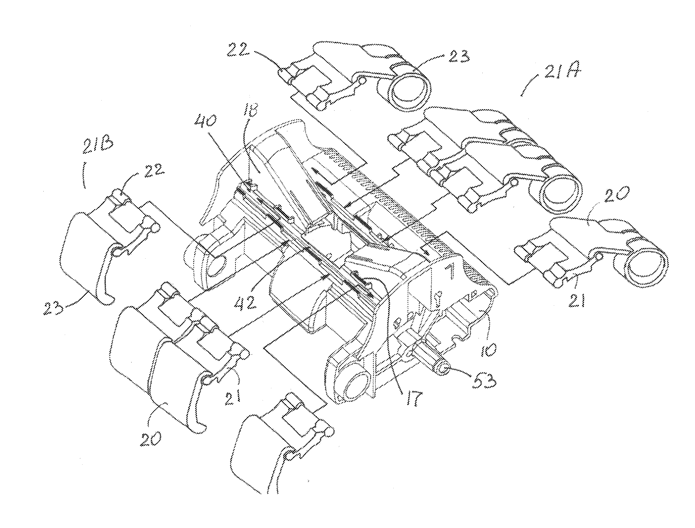
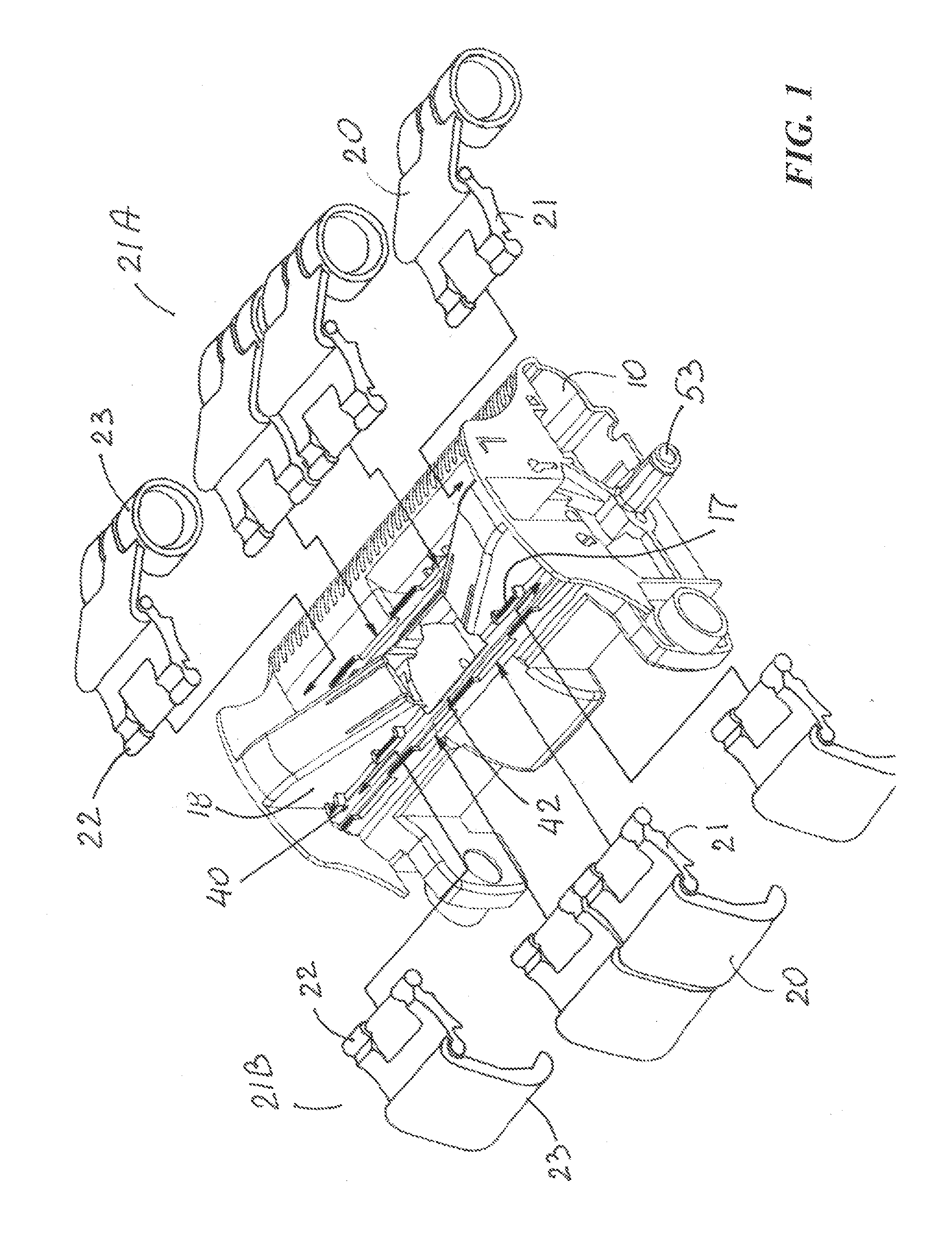
[0049]FIGS. 1-21 illustrate exemplary embodiments of aspects of the present invention for an improved swimming pool cleaner 100 of the type movable along an underwater pool surface 2 to clean debris therefrom.

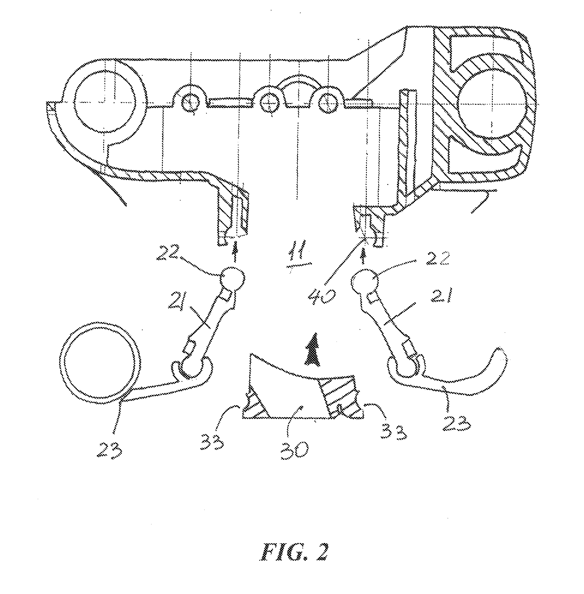
[0050]FIGS. 1 and 18-20 illustrate swimming pool cleaner 100 including a body 10 having a debris inlet 11 and a debris outlet 12. As best seen in FIGS. 1-3, a segmented skirt 20 includes a plurality of flap members 21 each of which extends from a proximal (or mounting) end 22 hinged to body 10 to a distal end 23 which is configured for extending along pool surface 2 such that skirt 20 forms with pool surface 2 a plenum from which water and debris are drawn into inlet 11, as best illustrated in FIG. 19. FIGS. 1-3, 5 and 18 show body 10 defining an elongate slotted cavity 40 extending between two ends 41 and pivotably holding proximal ends 22 of flap members 21 therewithin.

[0051]Prior to this invention, proximal ends of the skirt were clipped into the slotted cavity. Such clippin...


PUM

PropertyMeasurementUnit
sizeaaaaaaaaaa
pressureaaaaaaaaaa
timeaaaaaaaaaa

Abstract

A swimming pool cleaner including a body having a debris inlet and a debris outlet and defining an elongate slotted cavity pivotably holding proximal ends of flap members forming a segmented skirt which forms with the pool surface a plenum from which water and debris are drawn into the inlet. The slotted cavity is configured for strain-free insertion of the flap-member proximal ends into the cavity. A removable nozzle within the debris inlet and retaining the flap-member proximal ends in the cavity. A method for inlet to control debris-laden water flow. The cleaner further including a tool-free nozzle-mounting structure at the debris inlet removably retaining the nozzle within the debris inlet and a tool-free wheel-mounting assembly. a plurality of removable nozzles are interchangeably secured within the debris inlet, each nozzle having a flow opening sized differently from flow opening(s) of the other nozzle(s) to control debris-laden water flow.

Description

RELATED APPLICATIONS[0001]This application is a continuation-in-part of currently pending U.S. application Ser. No. 12 / 581,405, filed on Oct. 19, 2009, the entire contents of which are incorporate herein by reference.FIELD OF THE INVENTION[0002]The present invention relates to swimming pool cleaners and, more particularly, to automatic swimming pool cleaners movable along an underwater pool surface for purposes of cleaning debris therefrom. Still more particularly, this invention relates to swimming pool cleaners having the flow of water pumped and / or sucked by remote pumps into and through the pool cleaners.BACKGROUND OF THE INVENTION[0003]Automatic swimming pool cleaners of the type that move about the underwater surfaces of a swimming pool are driven by many different kinds of systems. A variety of different pool-cleaner devices in one way or another harness the flow of water, as it is drawn or pushed through the pool cleaner by the pumping action of a remote pump for debris coll...

Claims


Application Information

Patent Timeline
Patent Type & Authority Applications(United States)
IPC IPC(8): E04H4/16
CPCE04H4/1654E04H4/16E04H4/1636Y10T29/49863
Inventor RIEF, DIETER J.SCHLITZER, HANS RAINER
Owner HAYWARD IND INC
Why Eureka
Try Eureka