Automated fluid delivery system and method

a fluid delivery system and fluid technology, applied in the field of fluid systems, can solve the problems of predetermined oxygen flow rate, waste of oxygen, and often remaining unadjusted

Inactive Publication Date: 2013-06-20
RGT UNIV OF CALIFORNIA
View PDF17 Cites 210 Cited by
  • Summary
  • Abstract
  • Description
  • Claims
  • Application Information

AI Technical Summary

Benefits of technology

[0008]In one aspect of the present invention, a system of providing fluid to a user comprises distensible tubing, a flow controller coupled to the tubing and configured to control a flow of fluid through the tubing, and a fluid flow adjustment module connected to the tubing

Problems solved by technology

The flow rate of oxygen provided is predetermined and often remains unadj

Method used


Image

  • Automated fluid delivery system and method
  • Automated fluid delivery system and method
  • Automated fluid delivery system and method

Examples


Embodiment Construction

[0016]The following detailed description is of the best currently contemplated modes of carrying out exemplary embodiments of the invention. The description is not to be taken in a limiting sense, but is made merely for the purpose of illustrating the general principles of the invention, since the scope of the invention is best defined by the appended claims.

[0017]Various inventive features are described below that can each be used independently of one another or in combination with other features. However, any single inventive feature may not address any of the problems discussed above or may only address one of the problems discussed above. Further, one or more of the problems discussed above may not be fully addressed by any of the features described below.

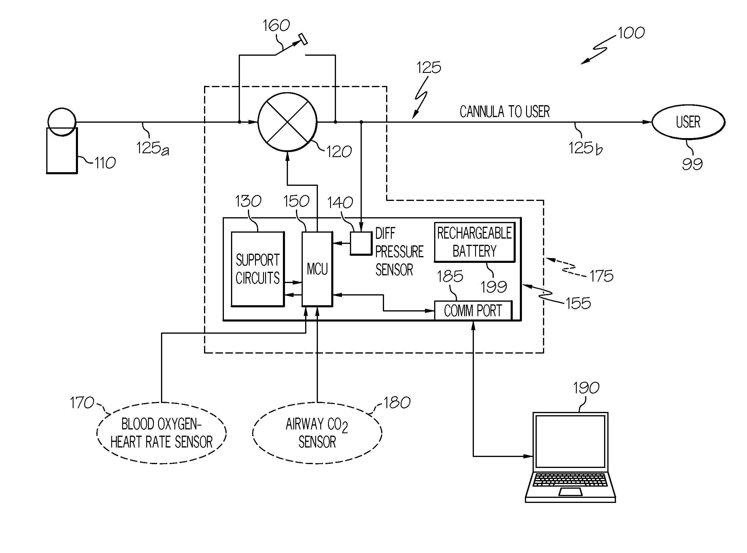
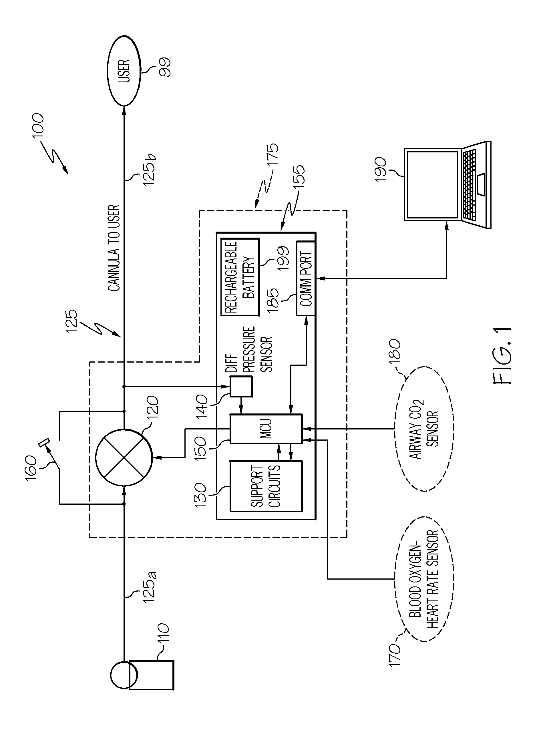
[0018]Broadly, embodiments of the present invention generally may provide an automated system adapted to provide an optimum bolus of oxygen based on measured needs of a user. In one aspect, the system may supply supplemental ox...


PUM


Abstract

An automated fluid delivery system and method are disclosed. The system includes distensible tubing, a flow controller, and a fluid flow adjustment module. The fluid flow adjustment module may be configured to detect differential pressure in the tubing and adjust the flow controller to provide an amount of fluid through the tubing during inhalation.

Description

CROSS-REFERENCE TO RELATED APPLICATION[0001]This application claims the benefit of priority of U.S. provisional patent application No. 61 / 372,411, filed, Aug. 10, 2010, the contents of which are incorporated herein by referenceBACKGROUND OF THE INVENTION[0002]The present invention generally relates to fluid systems, and more particularly, to an automated fluid delivery system.[0003]Some individuals benefit from the use of supplemental fluid delivery systems. For example, a person with chronic obstructive pulmonary disease (COPD), or other lung insufficiency, may need supplemental oxygen, which is commonly sourced from a compressed oxygen cylinder, to maintain a physiologically adequate degree of oxygen saturation in the blood. Supplemental oxygen delivery typically involves a tubing connection to a tank and a pressure regulator for an extended period of time. Others, for example, athletes, aircraft pilots, travelers at mountainous high altitudes, may need temporary oxygen supplement...

Claims


Application Information

Patent Timeline
IPC IPC(8): A61M16/08A61M16/20A61M16/00
CPCA61M16/12A61M16/204A61M2202/0208A61M2205/18A61M2205/8206A61M2230/005A61M2230/06A61M2230/205A61M2230/432A61M16/0057A61M16/0875A61M16/20A61M2016/0021A61M16/0677A61M16/125A61M2016/0027A61M2205/3358A61M16/1015A61M16/0858A61M16/0051A61M16/024
Inventor LISCHER, DAVID WILLIAMROBERTS, STEPHEN WINSTON
Owner RGT UNIV OF CALIFORNIA
Why Eureka
Try Eureka