Load and/or transport cart

a technology for transporting carts and loading and lowering, which is applied to hand carts, motorcycles, bicycles, etc., can solve the problems of limiting the range of action of carts, too large, and unsuitability, and achieves the effects of reducing the overall size, and improving handling

Inactive Publication Date: 2013-06-20
CONSTIN HANS PETER
View PDF4 Cites 28 Cited by
  • Summary
  • Abstract
  • Description
  • Claims
  • Application Information

AI Technical Summary

Benefits of technology

[0009]The object of the invention is to provide a and transport load cart in the form of a scooter, which ensures a greater range in combination with secure transport of bulky and heavy purchased goods with persons, while further reducing the overall size, improving handling and reducing the amount of force required.

Problems solved by technology

However, shopping carts can typically be moved only at the speed of a pedestrian, which greatly limits the range of action of the carts.
This is too bulky, however, and is not suitable for transporting heavy purchased goods such as beverage crates, for example.
Conventional scooters and kickboards are likewise not suitable for this.
All these known solutions have the same disadvantage, namely that the rollers do not have a separate drive and are therefore limited in terms of the range thereof, but also require the application of great force to transport heavy, bulky loads, and are even unsuitable for this.

Method used


Image

  • Load and/or transport cart
  • Load and/or transport cart
  • Load and/or transport cart

Examples


first exemplary embodiment

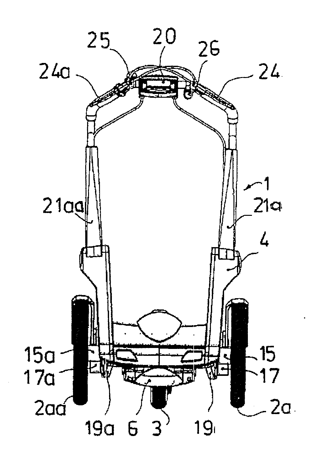
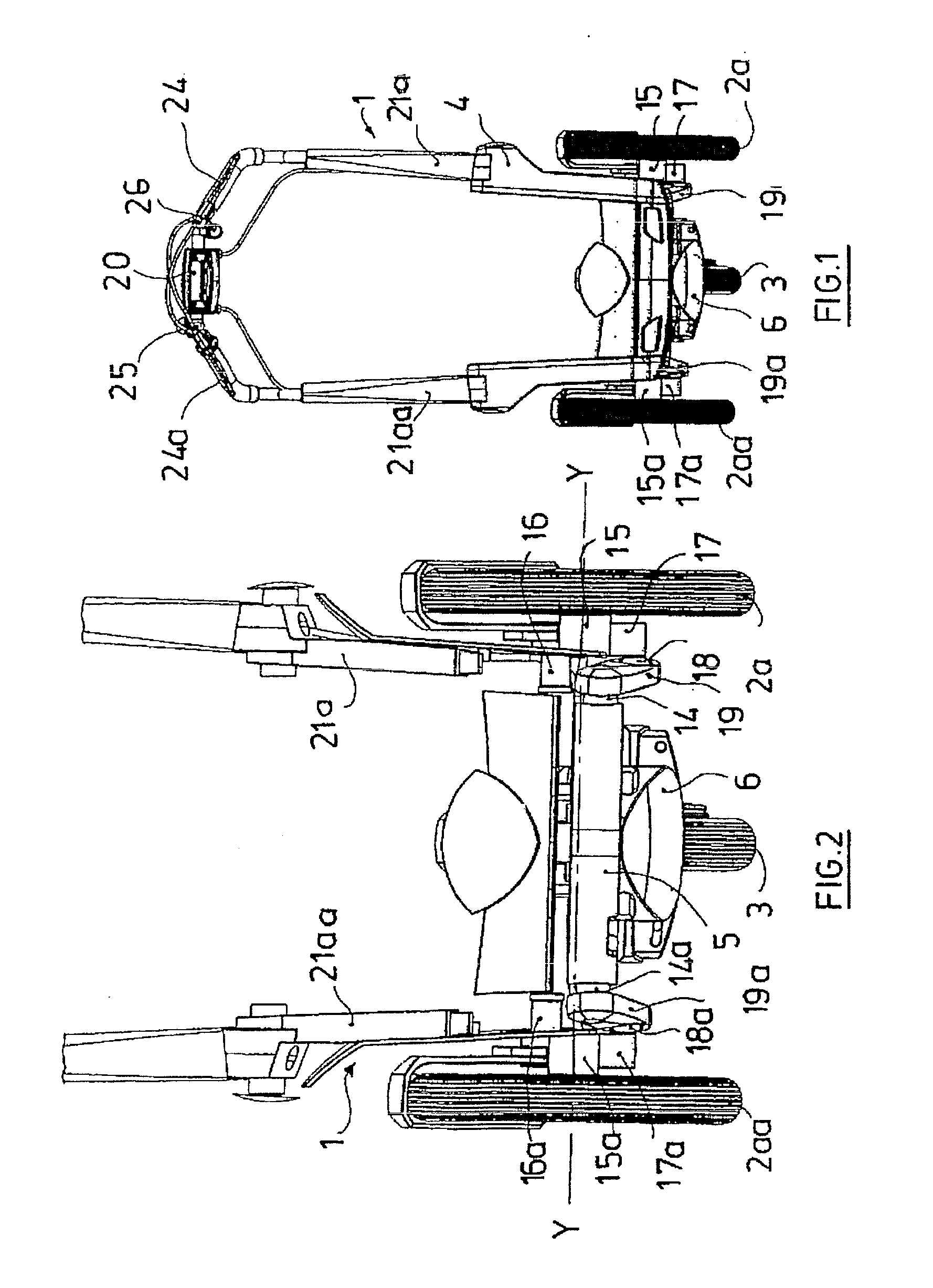
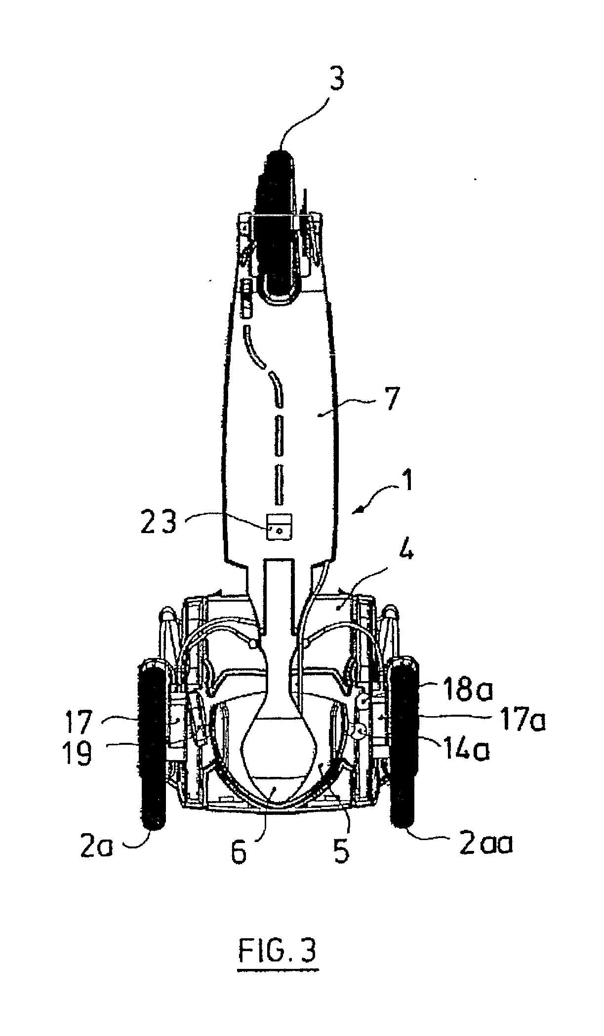
[0065]FIGS. 1 to 4 show the basic design of the load and transport cart 1 according to the invention comprising two front wheels 2a, 2aa and the rear wheel 3. The loading platform 4 is located between the two front wheels 2a and 2aa. A triangular steering plate 5 is disposed under the loading platform 4, under which the front part 6 of the footboard 7 is located. The loading platform 4 is rotatably connected via a steering-pivot pin 8 to the front part 6 of the footboard 7.

[0066]The steering plate 5 comprises an annular-segment shaped groove 9, in which the steering-pivot pin 8 of the front part 6 of the footboard 7 lies, a bore 10, in which a round pin 11 of the front part 6 of the footboard 7 lies, an elongated hole 12, in which the round guide pin 13 of the loading platform 4 lies, and two ball heads 14 and 14a, which are located opposite one another at the edge in rear corners (see FIGS. 5 to 8).

[0067]The two front wheels 2a and 2aa are rotatably mounted on the stub axles 15 and...

second exemplary embodiment

[0075]FIGS. 14 to 27 show an alternative embodiment of the load and transport cart according to the invention. To permit the reference characters to be distinguished from those of the first exemplary embodiment, an additional letter identifier is provided for reference characters that are otherwise the same.

[0076]The arrangement of loading platform, triangular steering plate, front part of the footboard, ball heads and swinging forks described in the first exemplary embodiment is the same.

[0077]FIGS. 14 to 16 show the load and transport cart 1a comprising the steering columns 21b and 21bb. As shown in FIG. 17, the load and transport cart 1a has a fixed handlebar 20a, which has a forwardly directed hand curve 29 in the center.

[0078]If the load and transport cart 1a is converted into a shopping cart by folding up and removing the footboard 7a, the shopping cart can be comfortably gripped and pulled by hand via the hand curve 29 without having to adjust the steering column 21b and 21bb...


PUM


Abstract

A load and transport cart includes, under a loading platform, a triangular steering plate and, therebelow, a front part of a footboard, wherein the steering plate has a bore, an annular-segment shaped groove, an elongated hole and two opposing first ball heads. The first ball heads each lie in an articulated manner in a respective bearing at one end of a respective steering lever and, at the other end of each lever is a bearing for a respective further ball head of a respective triangular swinging fork on a stub axle of which a respective front wheel is rotatably mounted, wherein each of the swinging forks is rotatably mounted on the loading platform via pivot pins, and wherein the steering axis is located in front of an imaginary axis and can be deflected to the left or right by the steering angle of 45°.

Description

BACKGROUND OF THE INVENTION[0001]The invention relates to a load and transport cart.[0002]It is known that shopping carts provide great help for transporting purchased goods without the purchased goods having to be carried. However, shopping carts can typically be moved only at the speed of a pedestrian, which greatly limits the range of action of the carts.[0003]A bicycle having a shopping basket or storage bags does enlarge the range of action for transport. This is too bulky, however, and is not suitable for transporting heavy purchased goods such as beverage crates, for example. Conventional scooters and kickboards are likewise not suitable for this.[0004]Document DE 10 2006 042 1129 A1 describes a load cart, which comprises three wheels, a footboard, which can be folded upward, and a loading surface on the front side, on which heavy, bulky loads can be loaded and transported, wherein the front wheels can be slanted relative to the roadway via beveled gear pairs during cornering...

Claims


Application Information

Patent Timeline
Patent Type & Authority Applications(United States)
IPC IPC(8): B62K11/00B62K3/00
CPCB62B1/002B62B1/008B62B1/12B62B3/027B62B5/0026B62K11/00B62B2202/12B62K3/002B62K15/006B62K19/46B62K2015/005B62B5/087B62K7/04B62K13/08
Inventor CONSTIN, HANS-PETER
Owner CONSTIN HANS PETER
Why Eureka
Try Eureka