Method and device for detecting touch screen

Active Publication Date: 2013-06-20
EGALAX EMPIA TECH INC
View PDF2 Cites 14 Cited by
  • Summary
  • Abstract
  • Description
  • Claims
  • Application Information

AI Technical Summary

Benefits of technology

[0026]3. Writing can be made more accurately at the expected locations, which provi

Problems solved by technology

Such a limitation therefore dictates the size of the pen head of the passive capacitive pen to be relatively large, which results in low accuracy when one wishes to write at a desired location.
During writing, the pen may tem

Method used


Image

  • Method and device for detecting touch screen
  • Method and device for detecting touch screen
  • Method and device for detecting touch screen

Examples


first embodiment

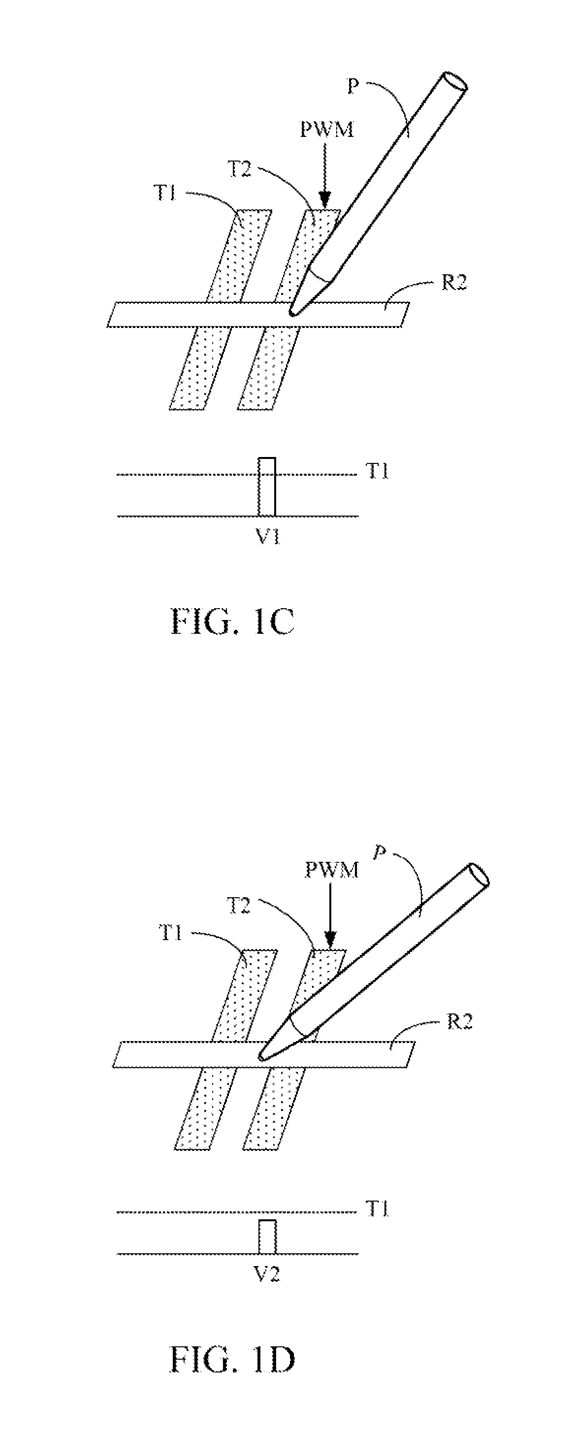
[0054]Referring to FIGS. 1C to 1E, a capacitive pen with a small pen head is shown. The pen head and the pen body of the capacitive pen P are in contact with each other, such that a hand holding the pen body can be capacitive coupled to a touch screen via the pen head. In addition, the diameter of the contact area of the pen head of the capacitive pen P with the touch screen is less than about 3 mm. In a preferred example of the present invention, the diameter of the contact area of the pen head of the capacitive pen P with the touch screen is about 2.2 mm. During mutual capacitive detection, when a driving signal (e.g. a pulse-width modulation (PWM) signal) is provided to a first conductive strip (e.g. a first conductive strip T2), changes in capacitive coupling at each intersection on the first conductive strip is detected through each second conductive strip (e.g. a second conductive strip R2) intersecting the first conductive strip. When the capacitive pen P approaches or touch...

second embodiment

[0078]Referring to FIGS. 3A and 3B, a capacitive pen 30 proposed by the present invention is shown. The capacitive pen 30 includes a conductive pen body 31 and a conductive pen head 32. The conductive pen head is in physical contact with the conductive pen body, such that when the conductive pen body is in contact with the hand or person holding the pen, the conductive pen head is coupled to the hand or human body via the conductive pen body, and is further coupled to ground through the human body. In an example of the present invention, the conductive pen head 32 is made by curing conductive fibers, for example, by optical or thermal curing after being bonded together. In addition, the conductive pen head 32 further includes a contact portion 33, wherein the degree of curing of the contact portion 33 is different from that of other non-contact portion of the conductive pen head 32. More specifically, the contact portion 33 is softer than the non-contact portion of the conductive pe...

third embodiment

[0087]Referring to FIGS. 4A and 4B, a capacitive pen proposed by the present invention is shown. The capacitive pen includes a conductive pen body 40 and a conductive pen head 41. Referring to FIG. 4A, when the pen head 41 is close to or in contact with a touch sensor, the conductive pen head 41 will be capacitively coupled to a driven conductive strip being provided with a driving signal (e.g. PWM), and then based on the capacitively coupled driving signal, the capacitive pen provides an output signal to the touch sensor via capacitive coupling during a period in which the driving signal is no longer provided to any driven conductive strip, as shown in FIG. 4B. The output signal will be capacitively coupled with the conductive strips of the touch sensor to provide detected signals. For example, the output signal is capacitively coupled with at least one first conductive strip Tx to provide a signal St, and with at least one second conductive strip Rx to provide a signal Sr. By scan...


PUM


Abstract

A detection method and device for a touch screen is provided. When a pen touching or approaching the touch screen is detected, only the location of the pen in a predetermined range is provided, and the locations of all other objects within the predetermined range are not provided, such as the location of a palm. Only if the pen and all the objects in the predetermined range are no longer detected, then the locations of objects other than the pen in the predetermined range are provided again.

Description

CROSS REFERENCE TO RELATED PATENT APPLICATION[0001]This patent application claims the domestic priority of the U.S. provisional application 61 / 577,175 filed on Dec. 19, 2011, and hereby incorporated by reference.BACKGROUND OF THE INVENTION[0002]1. Field of the Invention[0003]The present invention relates to a capacitive writing device, and more particularly, to a cordless capacitive writing device in phase with a touch sensor.[0004]2. Description of the Prior Art[0005]Referring to FIG. 1A, a conventional mutual capacitive sensor 10 is shown, which includes an insulating surface layer 11, a first conductive layer 12, a dielectric layer 13, a second conductive layer 14. The first conductive layer 12 and the second conductive layer 14 have a plurality of first conductive strips and a plurality of second conductive strips, respectively. Each of these conductive strips can be made up by a plurality of conductive pads 15 and connecting lines 19 connected to the conductive pads 15 in serie...

Claims


Application Information

Patent Timeline
IPC IPC(8): G06F3/0354
CPCG06F3/03545G06F3/0416G06F3/044G06F3/04166G06F3/04162G06F3/0442G06F3/0441G06F3/0488
Inventor CHANG, CHIN-FU
Owner EGALAX EMPIA TECH INC
Why Eureka
Try Eureka