Robotic System for Simulating a Wearable Device and Method of Use

a technology of wearable devices and robots, applied in the field of robots for simulating wearable devices and methods of use, can solve the problems of significant added inertia attached to the wearer's body, limited degree of freedom or output capacity of assistance, and used for rehabilitation or assisting human walking at low speed, so as to reduce the weight of parts, accurately and quickly model, and reduce the effect of weigh

Active Publication Date: 2013-06-20
MASSACHUSETTS INST OF TECH
View PDF8 Cites 122 Cited by
  • Summary
  • Abstract
  • Description
  • Claims
  • Application Information

AI Technical Summary

Benefits of technology

[0009]This invention has many advantages. For example, the actuation source employed by the robotic system of the invention is remote from the actuation delivery mechanism, thereby reducing the weight typically associated with motors powerful enough to deliver sufficient force to an actuation delivery mechanism fitted to a subject. By reducing the weight of the portions of the invention fitted to the subject, the subject is able to provide a much more natural gait during walking or running for modeling purposes. In addition, the robotic system and method of the invention enable an iterative process that allows modulation of force delivered to the actuation delivery mechanism fitted to the subject in response to feedback provided by sensors detecting physiological features of the subject during walking or running Such iterative feedback allows the control system of the robotic system and method of the invention to much more accurately and rapidly model exoskeletons, orthoses and prostheses wearable by a

Problems solved by technology

Conventional devices for lower extremity augmentation, rehabilitation and assistance have either limited degrees of freedom or limited output capacity, and thus can only be used for rehabilitation or assisting human walking at low speed.
Further, most of the multiple degrees-of freedom tethered devices have rigid linkage tran

Method used


Image

  • Robotic System for Simulating a Wearable Device and Method of Use
  • Robotic System for Simulating a Wearable Device and Method of Use
  • Robotic System for Simulating a Wearable Device and Method of Use

Examples


Embodiment Construction

[0037]The invention generally is directed to a robotic system for simulating a wearable device and to a method for simulating a wearable robotic device.

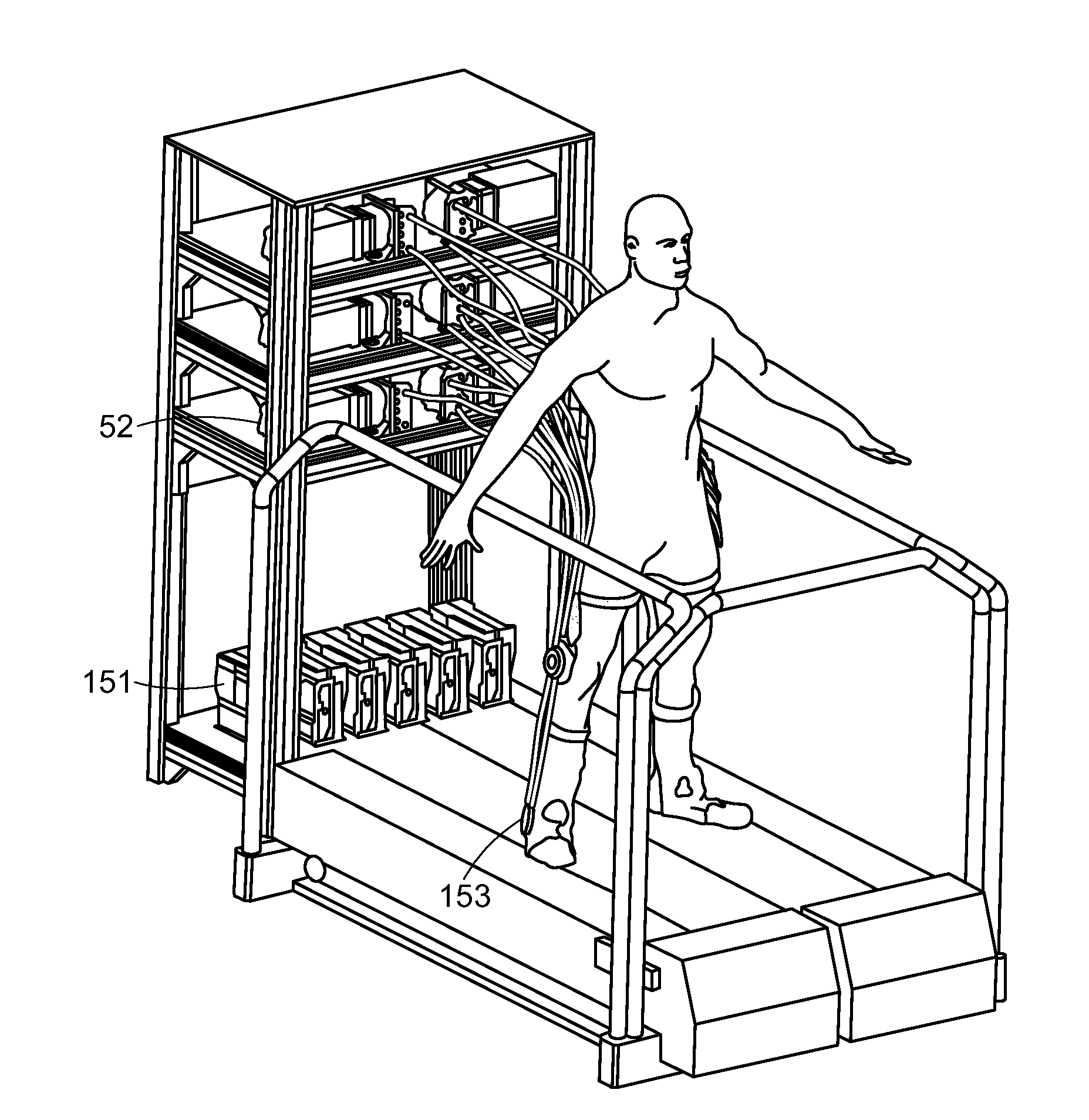
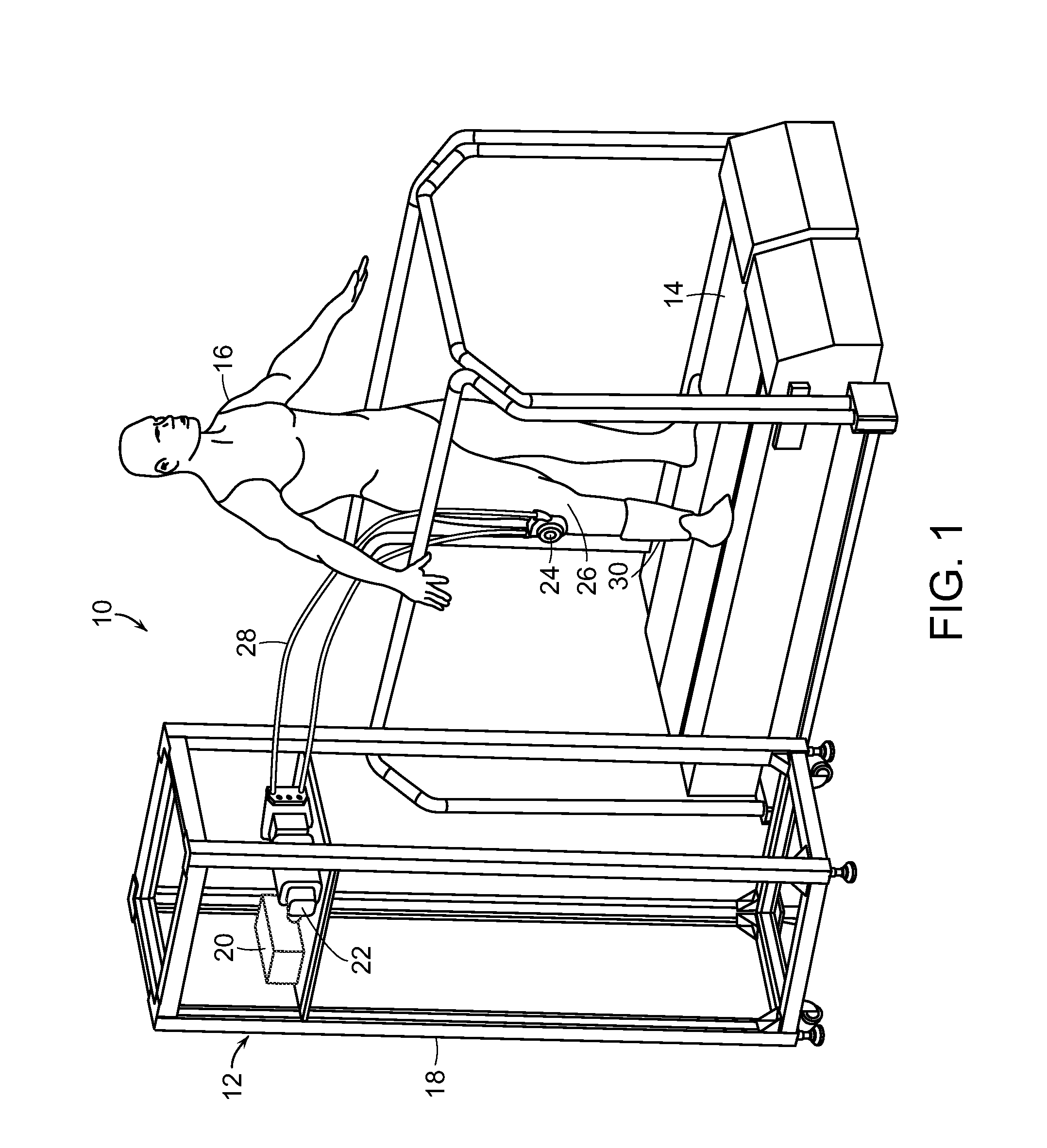
[0038]One embodiment of a robotic system for simulating a wearable device of the invention is shown in FIG. 1. As represented therein, robotic system 10 includes a suitable support, such as stand 12. Stand 12 includes treadmill 14. Optionally, force sensors or pressure sensors (not shown) detect footsteps of subject 16 on treadmill 14. Actuation source support 18 is adjacent to treadmill 14. Optionally, actuation source support 18 can be remote from treadmill 14. Control system 20 is mounted on actuation source support 18. Optionally, control system 20 can be mounted remotely from actuation source support 18.

[0039]Actuation source 22 is mounted on actuation source support 18. Actuation delivery mechanism 24 is fitted to subject 16 and is capable of delivering force to a prosthesis (not shown) or physiological joint 26 of subject 16, ...


PUM


Abstract

A robotic system for simulating a wearable device actuation delivery mechanism and the source removed from the actuation delivery mechanism that is linked to the actuation delivery mechanism by at least one cable. A sensing system detects a physiological feature of the subject and, based on feedback from the sensing system, a control system linked to both the sensing system and the actuation source modulates the actuation source, and thereby modulating actuation of the joint of a subject in response to the physiological future sensed by the sensing system. A method for simulating a wearable robotic system employs the robotic system of the invention to thereby provide a model on which to base design of an ambulatory prosthetic for a subject.

Description

[0001]This application claims the benefit of U.S. Provisional Application No. 61 / 578,177, filed on Dec. 20, 2011, the relevant teachings of which are incorporated herein in their entirety.BACKGROUND OF THE INVENTION[0002]Successful human augmentation has been a goal for several decades. However, researchers and engineers are still attempting to design an efficient extremity exoskeleton system that can enhance an able-bodied person's power and mobility, a promising prosthesis, or an effective rehabilitation device than can restore normal function to those with a disability. Such devices would have to generate either assistive or resistive force on a human body to perform normal functions.[0003]Typically, neither active nor passive wearable robots, such as active lower-extremity exoskeletons in [1-4] or passive and quasi-passive exoskeletons in [5-7], demonstrate a significant metabolic advantage for legged locomotion. One possible explanation is that it is not yet completely known wh...

Claims


Application Information

Patent Timeline
IPC IPC(8): A61H3/00
CPCA61H1/0255A61H3/00A61H1/0266A61H1/0277A61H1/0281A61H1/0285A61H1/0288A63B21/0081A63B21/1423A63B21/1449A63B21/1492A63B22/0235A63B23/03508A63B23/03541A63B23/047B25J9/0006A61H2201/1238A61H2201/1642A61H2201/165A61H2201/1676A61H2201/5061A61H2201/5064A61H2201/5071A61H2230/06A61H2230/50A61H2230/60A63B2220/10A63B2220/51A63B2220/56A63B2220/803A63B2220/805A63B2230/06A63B2230/50A63B2230/60A63B21/00178A63B21/00181A61H1/0262A63B21/008A63B21/4011A63B21/4025A63B21/4047
Inventor HERR, HUGH M.KUAN, JIUN-YIH
Owner MASSACHUSETTS INST OF TECH
Why Eureka
Try Eureka