
Automatic faucet

a faucet and photoelectric sensor technology, applied in the field of automatic faucets, can solve the problems of affecting the design flexibility of the automatic faucet, affecting the effect of the design flexibility, and deteriorating design flexibility, so as to prevent the erroneous start and stop of the water spouting. , the effect of simple configuration

Active Publication Date: 2013-06-27
TOTO LTD
View PDF3 Cites 10 Cited by
  • Summary
  • Abstract
  • Description
  • Claims
  • Application Information

AI Technical Summary

Benefits of technology

The present invention is a radio wave sensor that prevents a faucet from spouting water when it's not needed. It's easy to install and doesn't require complicated configurations.

Problems solved by technology

Thus, the automatic faucet using the photoelectric sensor has difficulty in obtaining enhanced response.
In the automatic faucet using the photoelectric sensor, in addition to the above problem that it is not easy to obtain enhanced response during start of water spouting, the necessity to install the photoelectric sensor at a position adjacent to the spout port due to its characteristics gives rise to another problem of deterioration in design flexibility.
That is, the photoelectric sensor and associated components such as wirings and electric components have to be installed within the conduit pipe at positions adjacent to the spout port, which imposes restrictions on design flexibility.
However, it is not easy to achieve adequate response.
That is, due to the layout where the radio wave sensor is installed on the sink side, if it is attempted to increase a radio field intensity in a vicinity of the spout port, the radio field intensity will be increased not only in the vicinity of the spout port but also all around the faucet, resulting in an excessively broad sensing range.
Thus, the automatic faucet having the radio wave sensor installed on the sink side has a problem that erroneous water spouting is more likely to occur in response to a water removing motion just after completion of hand washing, and a hand-lathering motion during hand washing.

Method used


Image

  • Automatic faucet
  • Automatic faucet
  • Automatic faucet

Examples


Embodiment Construction

[0061]With reference to FIGS. 1 to 20, an automatic faucet according to one embodiment of the present invention will now be described.

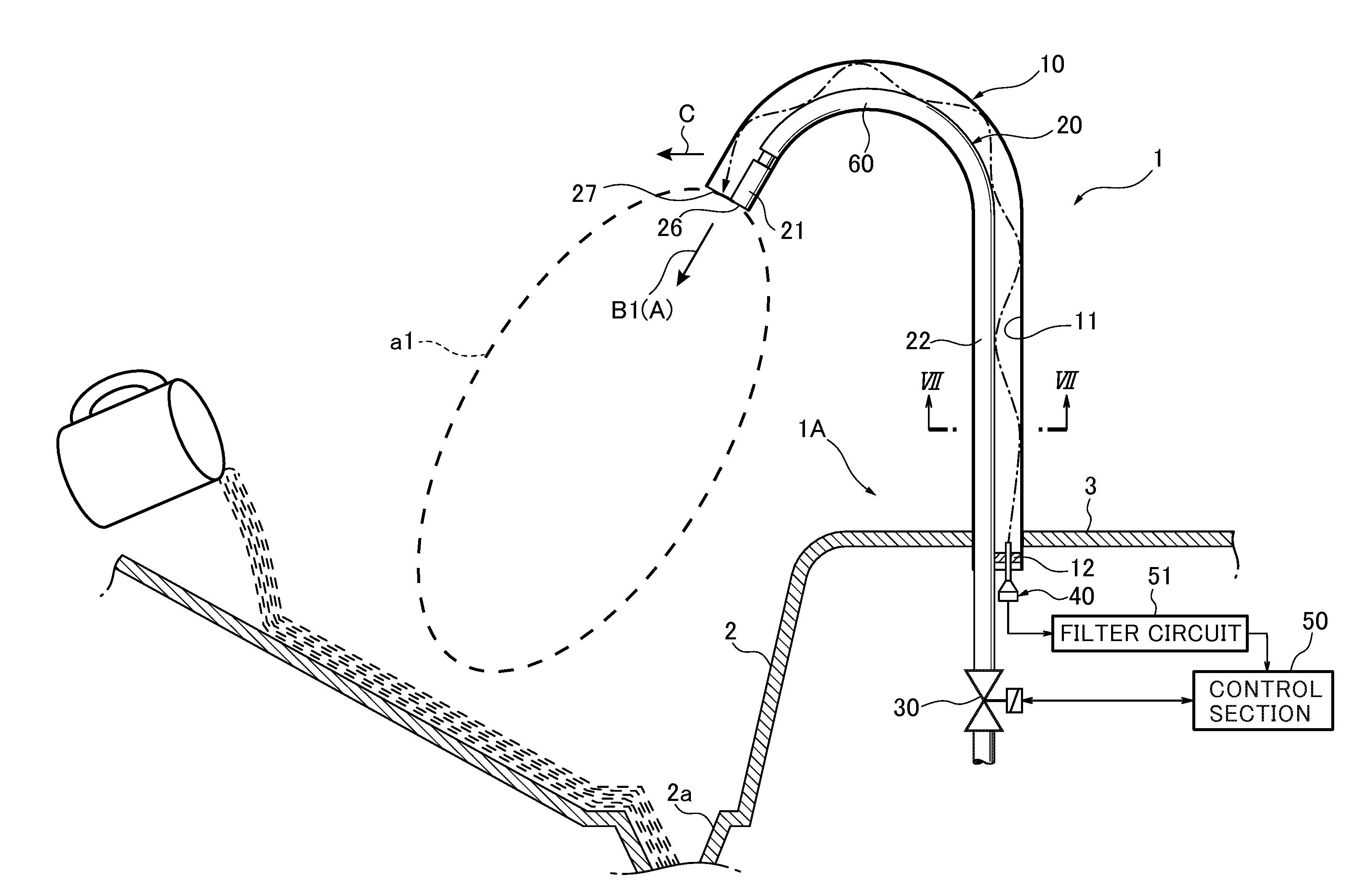
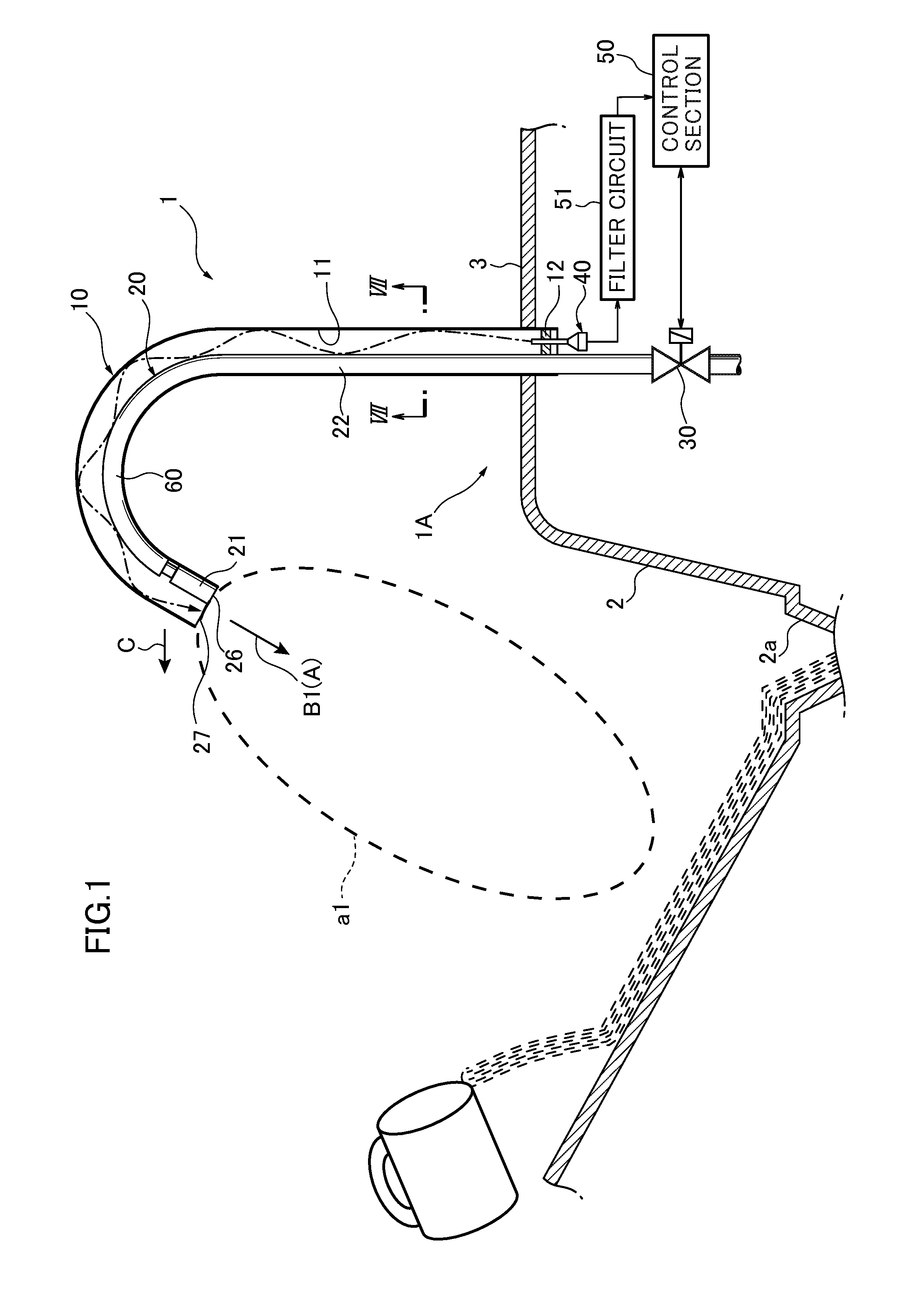
[0062]FIG. 1 illustrates a state in which the automatic faucet 1 according to this embodiment is attached to a washstand. The washstand comprises a sink 2 having a given concave shape, and a washstand base 3. The sink 2 has a sink outlet 2a provided in a bottom wall thereof.

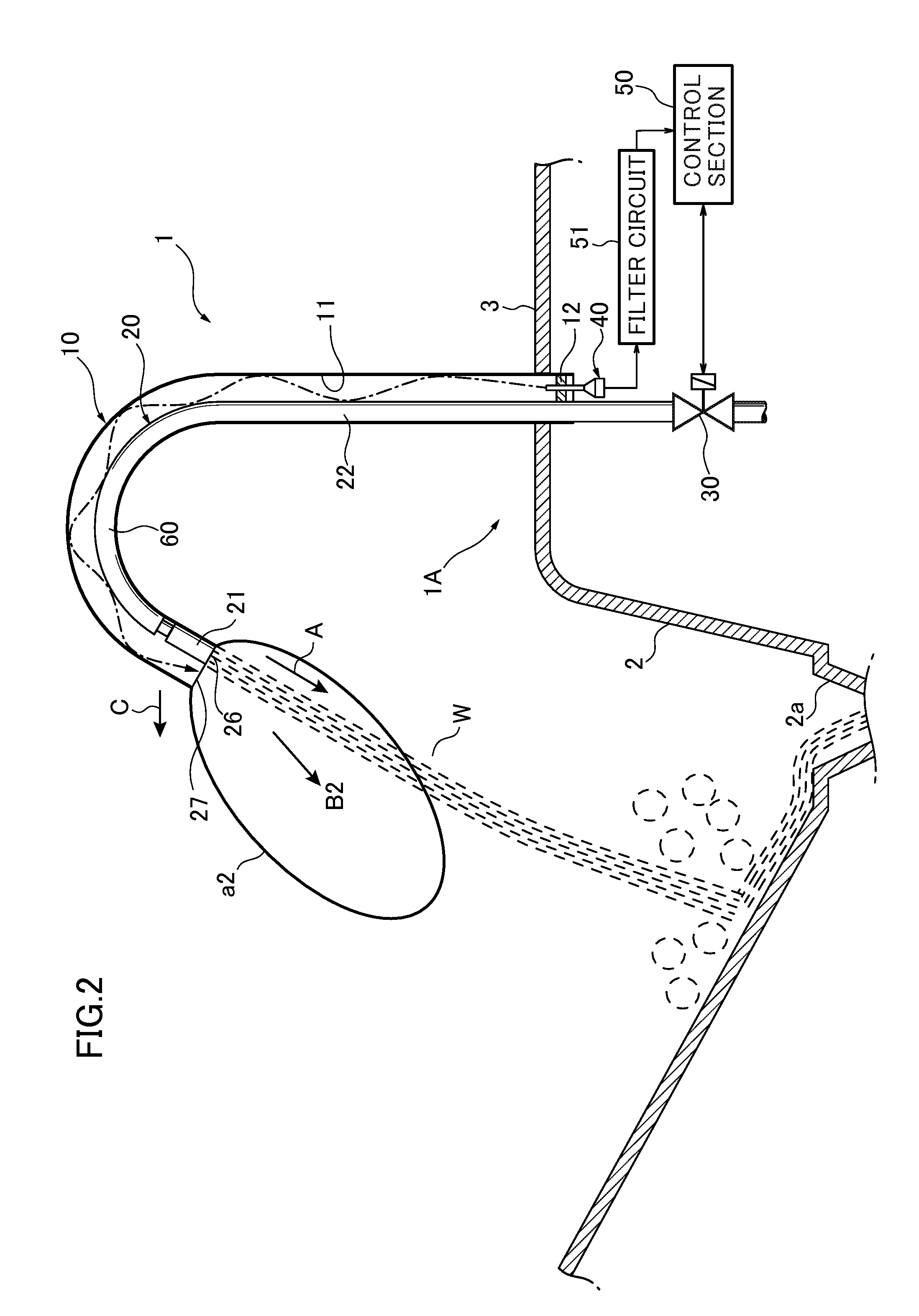
[0063]As illustrated in FIG. 1, the automatic faucet 1 according to this embodiment comprises: a faucet main unit 1A which includes a conduit pipe (faucet spout) 10 having a base end fixed to the washstand base (support body) 3 and extending toward a user side C, and a spout valve 30; a water pipe 20 inserted into the conduit pipe 10; a radio wave sensor 40 for detecting a user's behavior state including the presence or absence of a user or the presence or absence of usage; and a control section 50 for controlling an opening and closing action of the spout valve 30.

[0064]The condui...


PUM


Abstract

Provided is an automatic faucet using a radio wave sensor, which is capable of preventing erroneous stop of water spouting, with a simple configuration. The automatic faucet (1) has a radio wave propagation space, a radio wave emitting port (27), and directivity setting device. The directivity setting device is configured to direct a radio wave being emitted from the radio wave emitting port (27), in such a manner that, during a water stopping state, the emitted radio wave lies along a spouting direction (A) along which washing water is to be spouted from a spout port (26), and, during a water spouting state, a part of the radio wave emitted disposed offset in a direction C, with respect to the spout port (26) interferes with a region of a peripheral surface of a stream (W) facing in the direction C.

Description

TECHNICAL FIELD[0001]The present invention relates to an automatic faucet, and more particularly to an automatic faucet for automatically starting and stopping spouting water by using a radio wave sensor.BACKGROUND ART[0002]Heretofore, there has been known an automatic faucet for automatically starting and stopping spouting water by using a radio wave sensor (see, for example, the following Patent Document 1). Such an automatic faucet comprises a photoelectric sensor installed inside a distal end of a conduit pipe. When a user inserts his / her hand within a sensing range of the photoelectric sensor, the photoelectric sensor senses the presence of the hand, and, in response to the sensing, spouting of water from a spout port is automatically started. Then, when the user pulls out the hand from the sensing range, the photoelectric sensor ceases to sense the presence of the hand, and thereby the spouting of water from the spout port is automatically stopped.[0003]Meanwhile, in the autom...

Claims


Application Information

Patent Timeline
IPC IPC(8): E03C1/05
CPCE03C1/057
Inventor MURATA, KENSUKETSUBOI, HIROSHITSUIKI, SHOICHIMASAHIRA, YUYA
Owner TOTO LTD
Learn More