Firearm sight mount

Active Publication Date: 2013-06-27
SELLMARK CORP
View PDF40 Cites 30 Cited by
  • Summary
  • Abstract
  • Description
  • Claims
  • Application Information

AI Technical Summary

Benefits of technology

[0005]In some cases, it may be advantageous to be able to offset or move a sight out of alignment or to an offset position whereby another sight mounted on the firearm, such as the “iron sights,” can be used. In other instances, it may be desirable to remove the sight entirely. Accordingly, sight mounts have been provided with a hinge to provide the offsetting capability and with quick-detach features that a

Problems solved by technology

Some of the more modern sights are of limited or special purpose, such as night sights, so that

Method used


Image

  • Firearm sight mount
  • Firearm sight mount
  • Firearm sight mount

Examples


Embodiment Construction

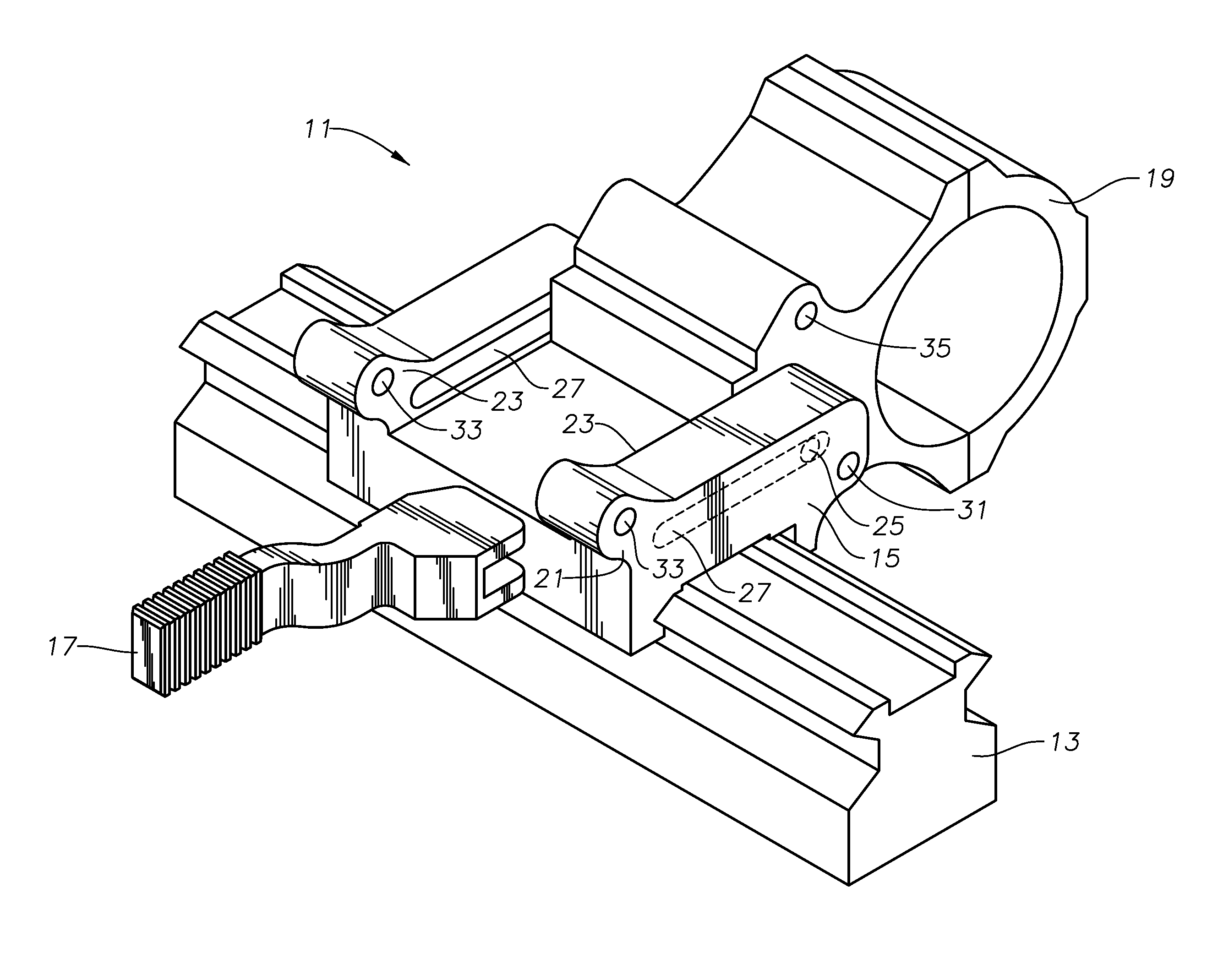
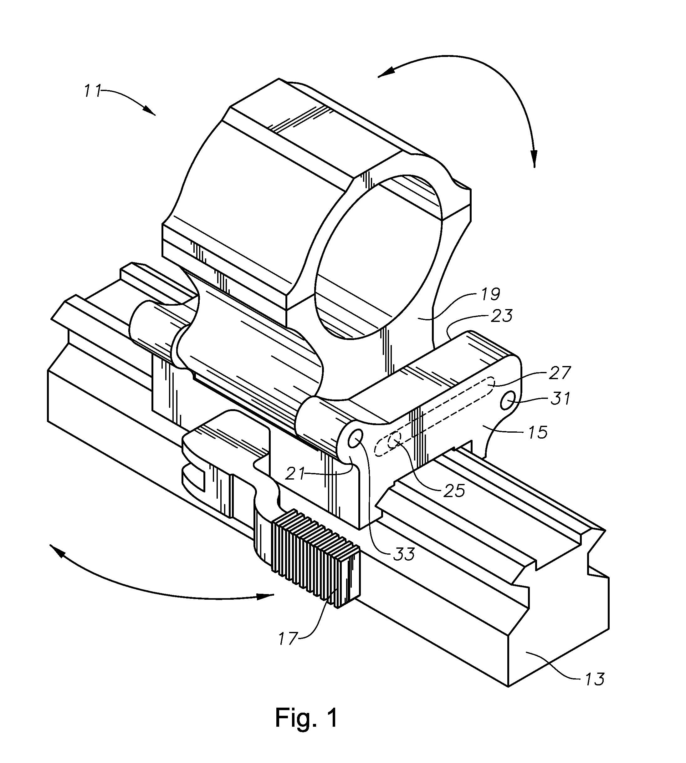
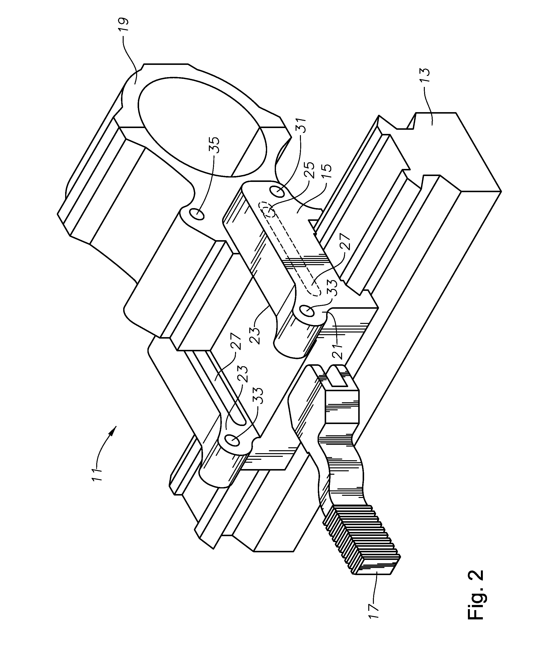
[0018]Referring now to the Figures, and particularly to FIGS. 1 and 2, a sight or sighting device mount 11 according to an exemplary embodiment of the present invention is shown. Mount 11 is secured to a rail 13 on a firearm (not shown). Rail 13 may be any of a number of conventional configurations including those known as “Weaver” or “Picatinny” rails that are commonly provided on firearms for mounting accessories to the weapon. The rail may be on a rifle, shotgun, or handgun, or even an archery bow (which falls into the definition of firearm for this purpose). Rail 13 is aligned with the sight axis, bore or sight line of the firearm so that anything mounted collinearly on it will also be aligned with the axis, subject to fine adjustment (commonly known as “sighting-in” or “zeroing” the weapon).

[0019]The sight or sighting device may comprise any of a number of well-known devices such as telescopic sights, laser sights, reflex, holographic or “red-dot” sights, infrared or other “nig...


PUM


Abstract

A sight base is configured to receive and secure a sighting device and is coupled to a base by a pin running in each of the grooves and rotatable about the pins between an aligned position with the base extending between the parallel walls and the optical device aligned with the sighting axis, and a deployed position rotated away from the aligned position. A detent releasably retains the sight base in the aligned position. A clamp member is carried on the lower extent of the base, and releasably engages the rail with selectively movable to tighten and secure the clamp and base to the rail. A lever is coupled to the base and to the clamp member, and has a camming surface configured to move the movable portion of the clamp into and out of engagement with the rail in response to actuation of the lever. The camming surface of the lever bears on a resilient surface carried by the base.

Description

BACKGROUND OF THE INVENTION[0001]1. Field of the Invention[0002]The present invention relates generally to mounting devices for firearm sights or sighting devices. More particularly, the present invention relates to such mounting devices having quick-detach and offset features that increase the versatility of the sight mounted using the device.[0003]2. Summary of Prior Art[0004]For decades various mounting devices have been used to mount telescopic sights to rifles. More recently, different types of sights, including “night-vision,” laser, and holographic sights, have been mounted to a variety of firearms, including handguns and shotguns in addition to rifles. Some of the more modern sights are of limited or special purpose, such as night sights, so that their use is not optimal in all conditions and replacement or alternative sights are desirable.[0005]In some cases, it may be advantageous to be able to offset or move a sight out of alignment or to an offset position whereby anothe...

Claims


Application Information

Patent Timeline
IPC IPC(8): F41G1/387F41G1/00
CPCF41G11/003F41G11/001
Inventor LI, DAOHAISELLERS, JAMESHORTON, JONATHAN
Owner SELLMARK CORP
Why Eureka
Try Eureka