Duct detector

a technology of duct detectors and detectors, applied in the field of duct detectors, can solve the problems of maintenance personnel returning to these difficult working conditions, affecting the operation of the maintenance staff, and affecting the operation of the detector

Active Publication Date: 2013-06-27
GARRETT THERMAL SYST LTD
View PDF10 Cites 22 Cited by
  • Summary
  • Abstract
  • Description
  • Claims
  • Application Information

AI Technical Summary

Benefits of technology

[0021]The units may include cooperable mating structure by which the units are coupled when in the close coupled configuration. The port unit preferably includes a housing, and the detector unit preferably includes a housing. In this case in the close coupled configuration the housing of the port unit and detector unit are engaged with each other. Engagement can be direct, or via an intermediate member, such as a gasket or the like, or via connector that holds the housings in a fixed relationship with each other. The connector could be separable or removable to allow the units to be separated. The connector could include one or more short pipes connecting the ports of each unit to a corresponding port the other unit. The connectors are preferably received internally within the ports and provide mechanical engagement between the units and prevent leakage from the ports, when connected in the close coupled configuration.

Problems solved by technology

HVAC ducts are often mounted within difficult working environments in roof spaces and the like.
As such, installing duct detectors can be difficult, and the installation of the detector is sometimes compromised due to these difficult working conditions.
Moreover, duct detectors require maintenance from time to time, meaning that periodically maintenance personnel must return to these difficult working conditions.

Method used


Image

  • Duct detector
  • Duct detector
  • Duct detector

Examples


Embodiment Construction

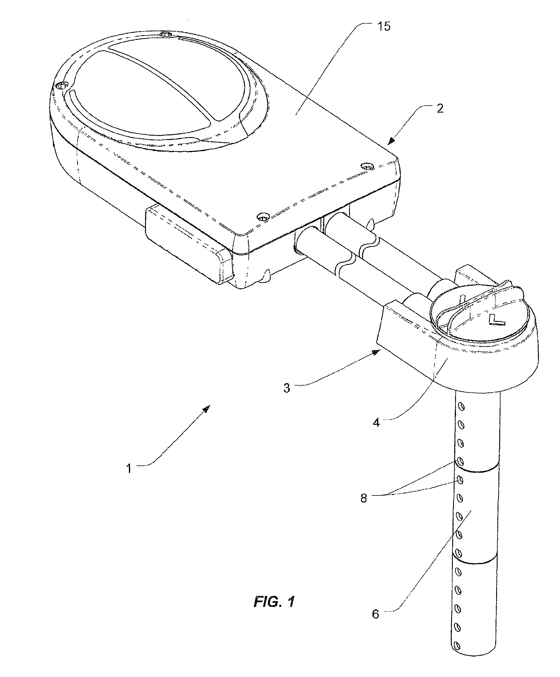
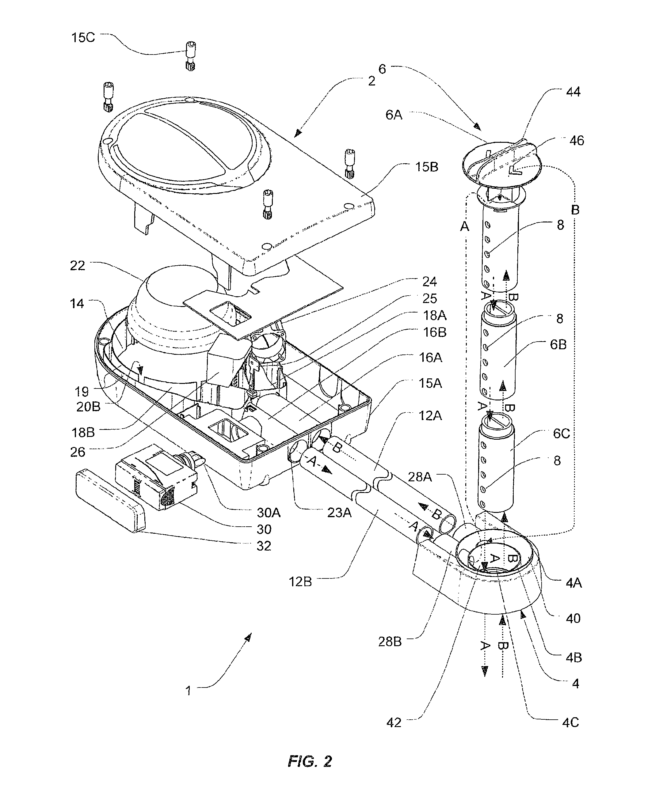
[0050]FIGS. 1 and 2 illustrate a duct detector 1 in accordance with a preferred embodiment of the invention. The duct detector 1 includes a detector unit 2 and a probe arrangement in the form of a probe unit 3 which is separable from the detector unit 2. A pair of conduits 12A and 12B connect the detector unit 2 and the probe unit 3 to allow the flow of fluid between them.

[0051]The detector unit 2 includes a detection region 14. A detection region is a region in which fluid is analysed. In this embodiment, the detection region has a detector module in the form of a point (or spot) detector mounted in it. Alternatively, by way of example, the detection region might be a detection chamber of an optical smoke detector or other volume.

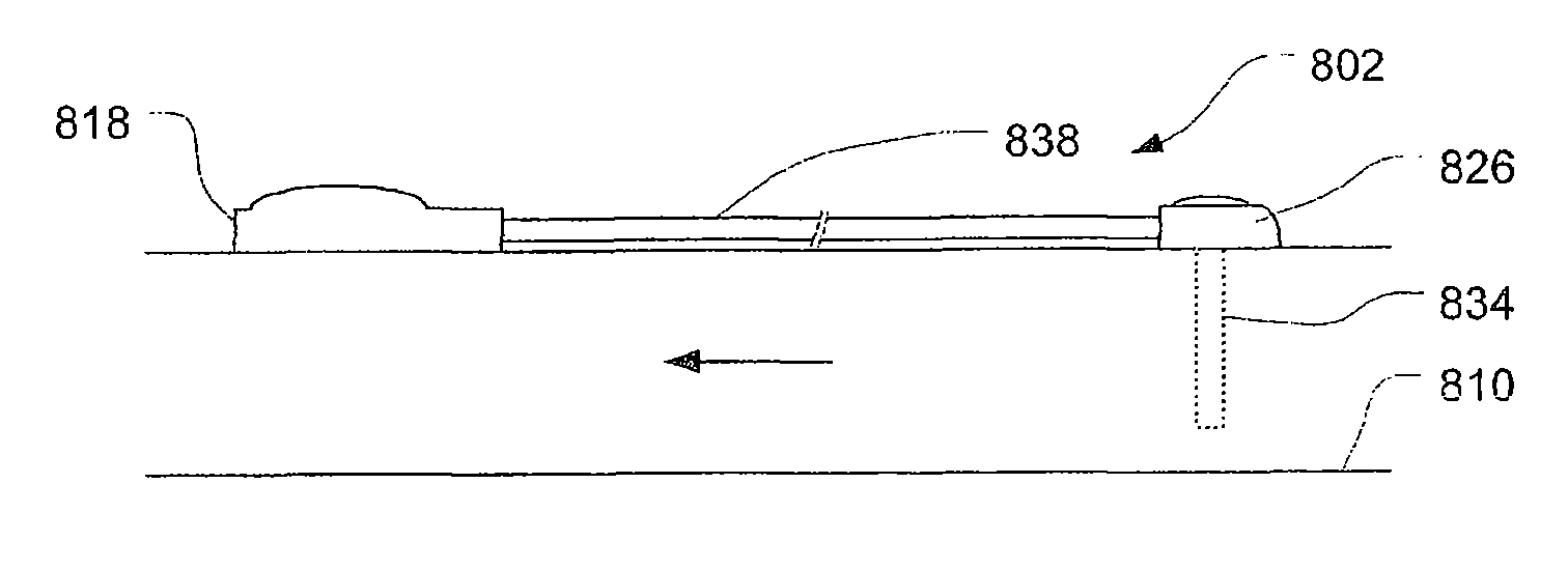
[0052]The units 2, 3 are each mountable to the exterior of an HVAC duct. The probe unit 3 includes an elongate probe 6 which, in use, projects through an aperture in the wall of the duct into the interior of the duct. The probe 6 includes a series of ports...


PUM

PropertyMeasurementUnit
structureaaaaaaaaaa
pressureaaaaaaaaaa
volumeaaaaaaaaaa

Abstract

There is described a duct detector and components for duct detectors. In one form the duct detector includes: a port unit and detector unit. The port unit is mountable to a duct in use so as to position one or more ports in the duct. The detector unit includes a detection region. The port unit and detector unit are reconfigurable between a close coupled configuration and a separated configuration in which the units are mountable with a variable separation between them and coupled by one or more elongate conduits to provide fluid communication between the units.

Description

FIELD OF THE INVENTION[0001]The invention relates to duct detectors and components for duct detectors.BACKGROUND OF THE INVENTION[0002]Duct detectors are a form of a detector mountable to a duct to provide an indication of a characteristic of the fluid flowing in the duct. For example, a duct detector in the form of a smoke detector can be mounted to a heating ventilation air-conditioning (HVAC) duct to detect smoke therein. Such an arrangement can provide an early indication of smoke in the HVAC system thereby enabling the HVAC system to be shut down to prevent smoke from one portion of the building being distributed about the building by the HVAC system.[0003]HVAC ducts are often mounted within difficult working environments in roof spaces and the like. As such, installing duct detectors can be difficult, and the installation of the detector is sometimes compromised due to these difficult working conditions. For example, structure defining an HVAC plenum for dividing and directing...

Claims


Application Information

Patent Timeline
Patent Type & Authority Applications(United States)
IPC IPC(8): G01N1/22F16L55/00
CPCG01N1/2247G01N1/26F16L55/00G08B17/117G08B17/10G08B17/113
Inventor WILLIAMSON, ALASDAIR JAMES
Owner GARRETT THERMAL SYST LTD
Why Eureka
Try Eureka