

Multi-directional input device
a multi-directional input and input device technology, applied in the field of multi-directional input devices, can solve the problems of difficult precise detection of b>2/b> oscillation, complicated configuration, etc., and achieve the effect of increasing the capacitance of the operation body by changing the capacitan
- Summary
- Abstract
- Description
- Claims
- Application Information
AI Technical Summary
Benefits of technology
Problems solved by technology
Method used
Image

Examples
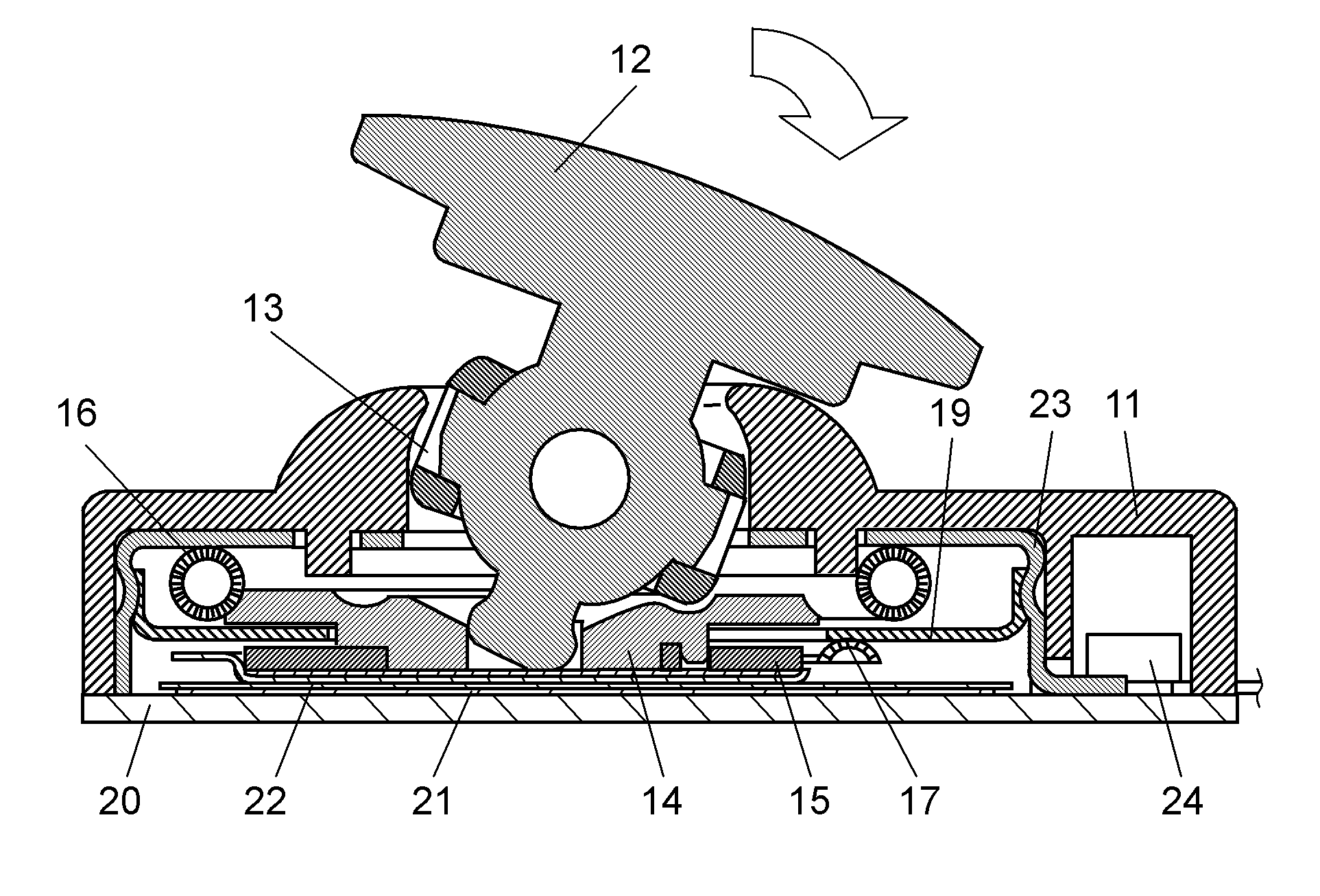
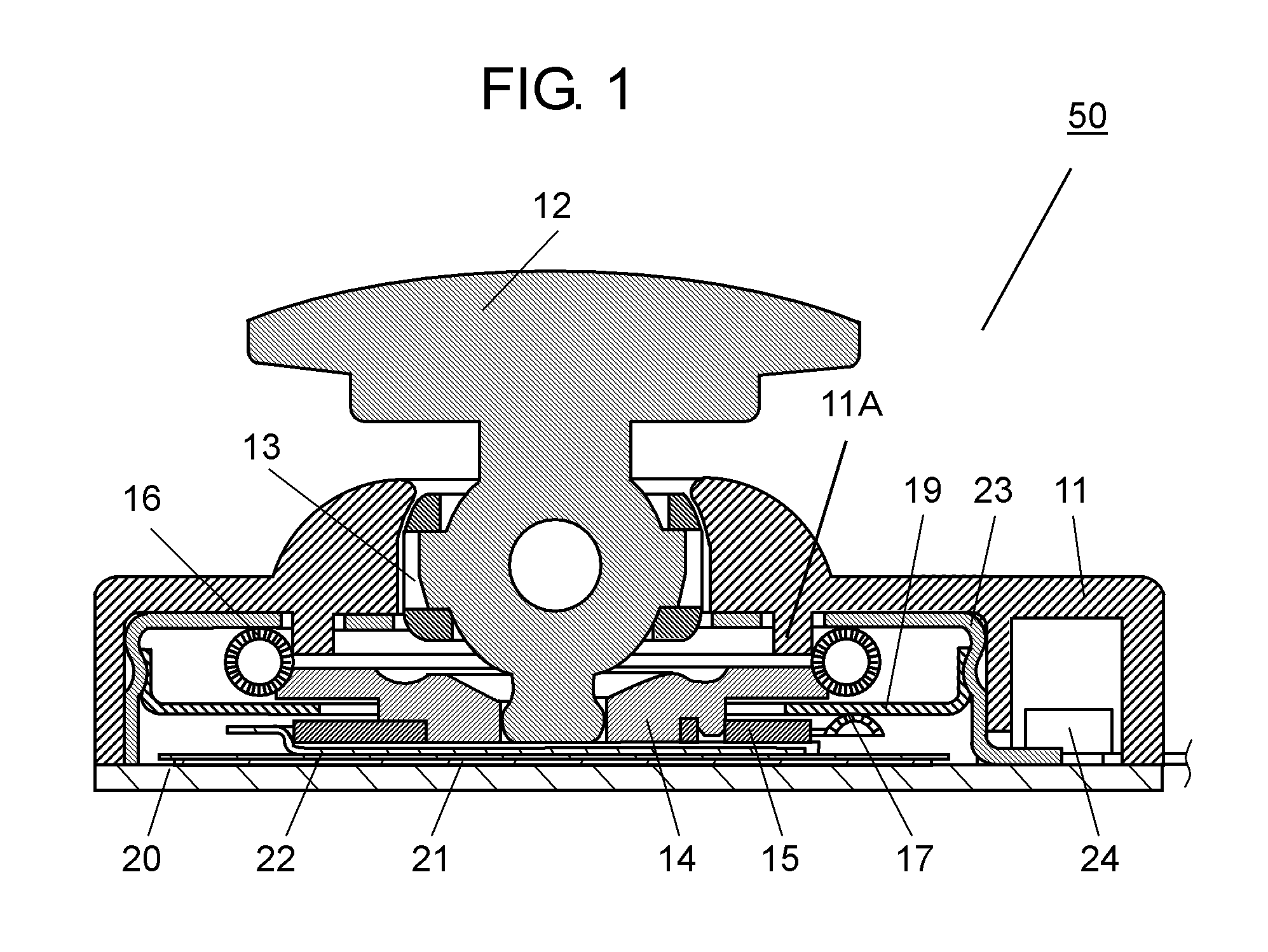
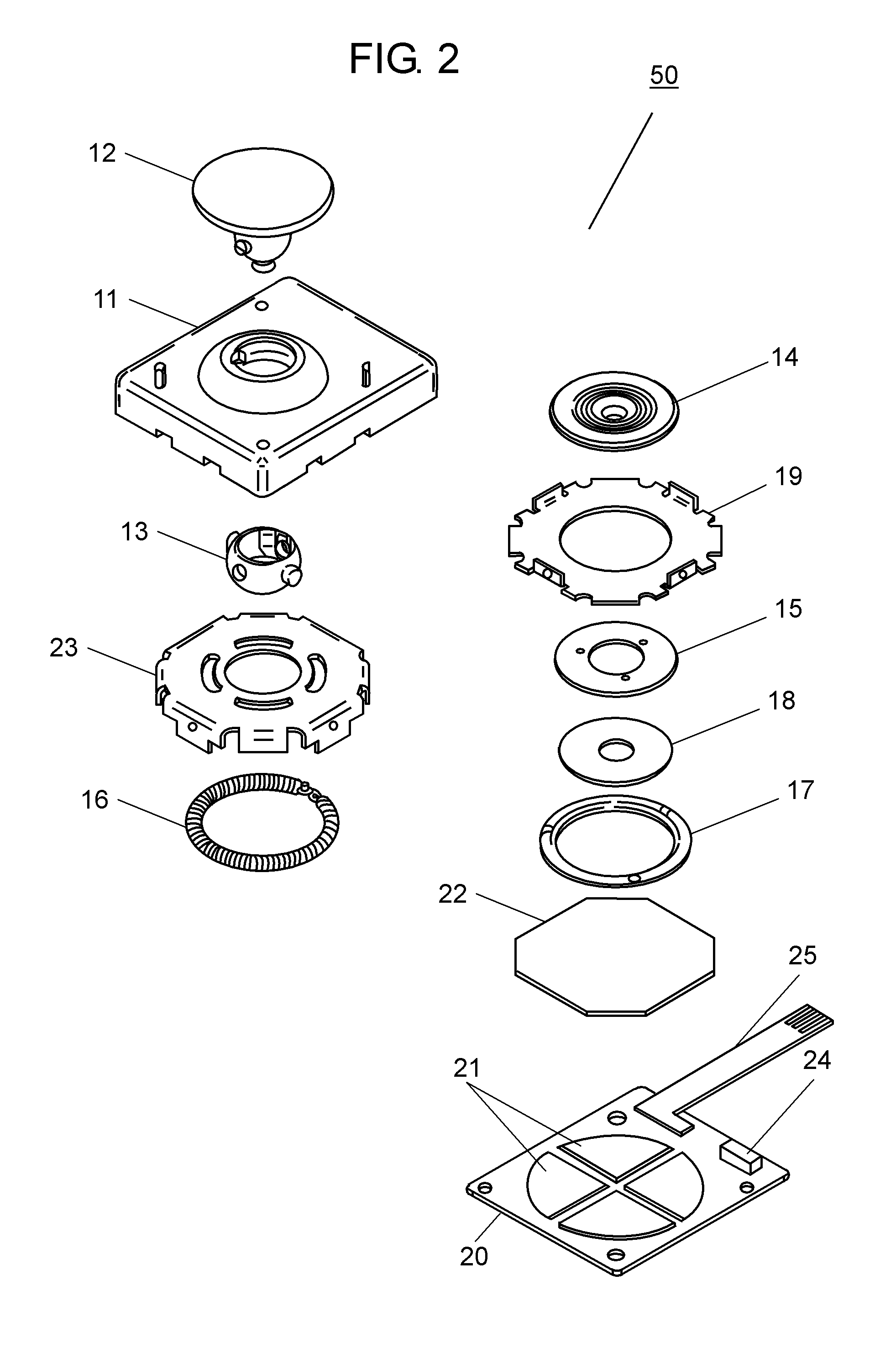
case 11
[0032]Case 11 is formed in a substantially box shape whose lower surface is open and made of insulating resin such as ABS and polybutylene terephthalate. Operation body 12 is made of insulating resin such as polyoxymethylene and ABS. A lower part of operation body 12 is inserted into case 11 through an insertion hole in a center of an upper surface.
[0033]Oscillation body 13 is formed in a substantially cylinder shape and made of insulating resin. A pivot shaft of an outer periphery of oscillation body 13 is inserted into a support hole of case 11, so that oscillation body 13 is locked onto case 11 oscillatably in the left and right direction. A pivot shaft of an outer periphery of operation body 12 is inserted into a support hole of oscillation body 13, so that operation body 12 is locked onto oscillation body 13 oscillatably in the front and rear direction. Thereby, operation body 12 is installed in case 11 oscillatably in multiple directions.
[0034]Sliding body 14 is made of insula...
PUM
 Abstract
Description
Claims
Application Information