Chromatic point sensor configuration including real time spectrum compensation

Active Publication Date: 2013-06-27
MITUTOYO CORP
View PDF3 Cites 15 Cited by
  • Summary
  • Abstract
  • Description
  • Claims
  • Application Information

AI Technical Summary

Benefits of technology

The present invention provides a system and method to compensate for variations in material spectral reflectivity and errors associated with light source variations in real-time, using spectral profile data. This invention is easier to use and provides more accurate and robust error compensation compared to previous methods. The disclosure of the patent does not mention errors due to material spectral reflectivity variations and does not propose a system configuration or method to compensate for such errors.

Problems solved by technology

The workpiece material component may characterize errors associated with workpiece specific spectral reflectivity variations, for example, in addition to other potential errors.

Method used


Image

  • Chromatic point sensor configuration including real time spectrum compensation
  • Chromatic point sensor configuration including real time spectrum compensation
  • Chromatic point sensor configuration including real time spectrum compensation

Examples


Embodiment Construction

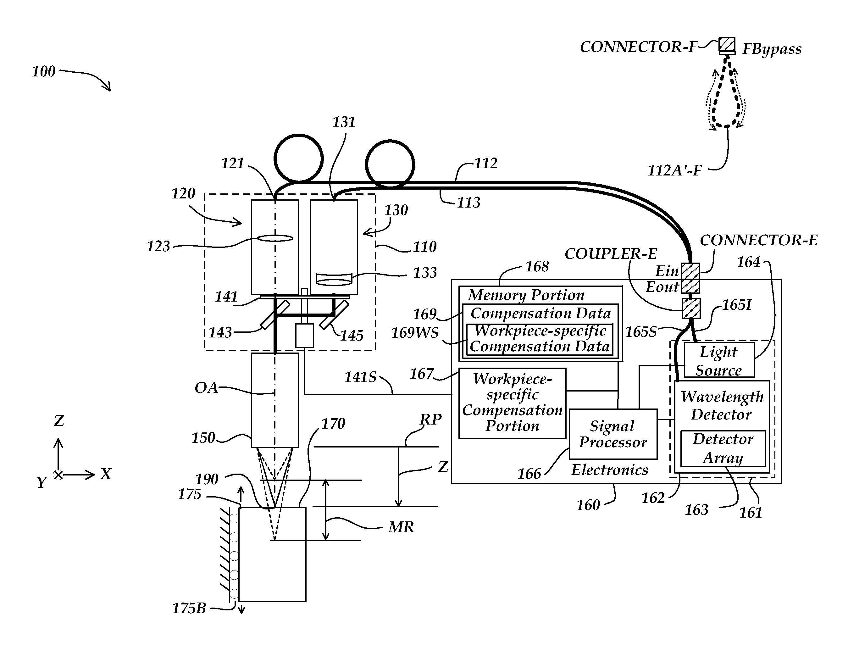
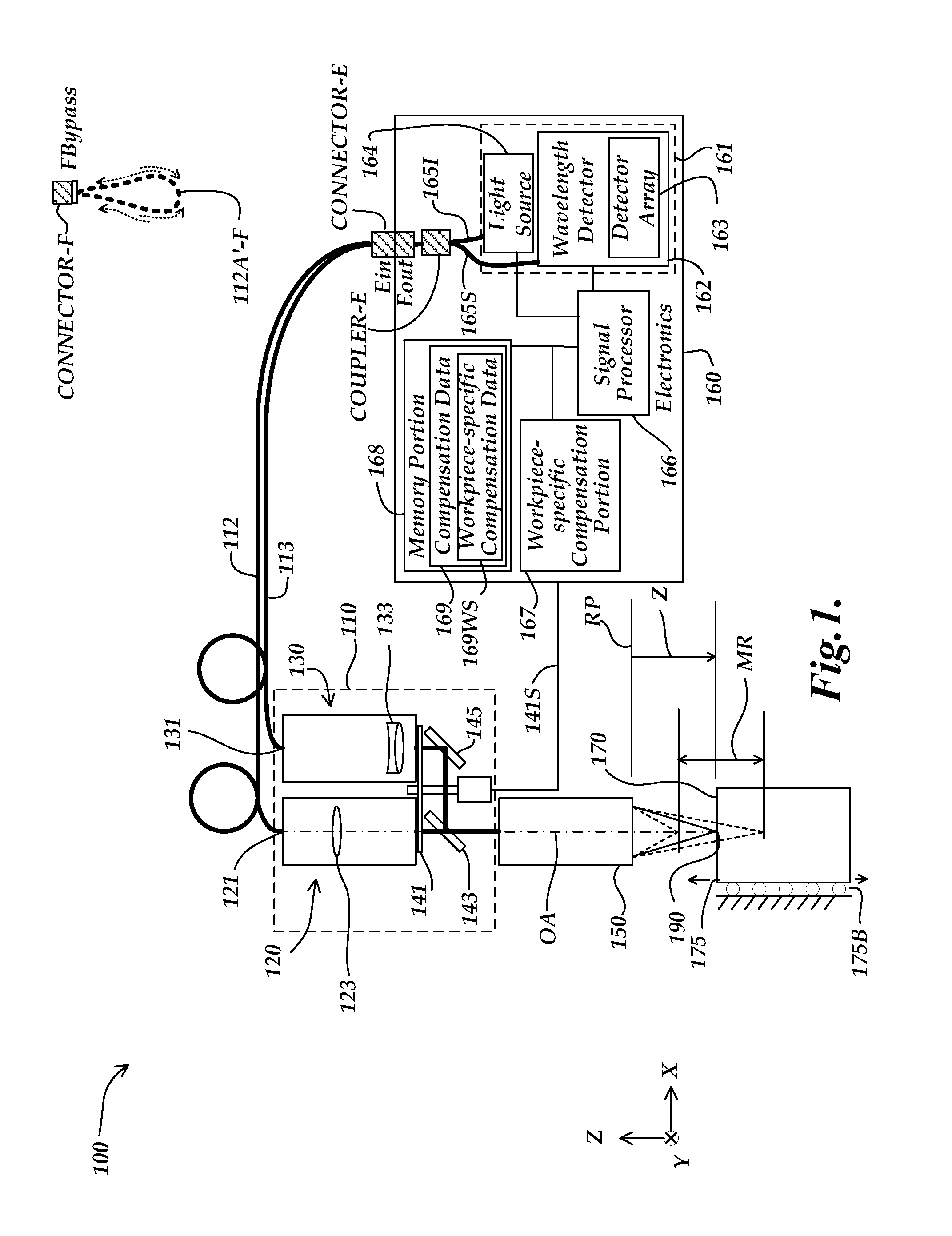
[0036]FIG. 1 is a block diagram of a first exemplary embodiment of a chromatic point sensor (CPS) system 100. As shown in FIG. 1, the chromatic point sensor system 100 includes a dual path optical portion 110, a switching element 141 and an electronics portion 160 which comprises a source+detector subsystem 161 and a light source 140. The dual path optical portion 110 comprises a first confocal optical path 120 and a second optical path 130. The first confocal optical path 120 comprises a chromatically dispersive optical element 123. The second optical path 130 comprises a non dispersive optical element 133. In some embodiments, the non dispersive optical element 133 may comprise an achromat.

[0037]The source+detector subsystem 161 comprises a wavelength detector 162, the CPS wavelength detector 162 comprising a plurality of pixels distributed along a measurement axis of the CPS wavelength detector 162, the plurality of pixels receiving respective wavelengths and providing output spe...


PUM


Abstract

A chromatic point sensor system configured to compensate for potential errors due to workpiece material effects comprises a first confocal optical path including a longitudinally dispersive element configured to focus different wavelengths at different distances proximate to a workpiece; a second optical path configured to focus different wavelengths at substantially the same distance proximate to the workpiece; a light source connected to the first confocal optical path; a light source connected to the second optical path; a first confocal optical path disabling element; a second optical path disabling element; and a CPS electronics comprising a CPS wavelength detector which provides output spectral profile data. The output spectral profile data from the second optical path is usable to compensate output spectral profile data from the first confocal optical path for a distance-independent profile component that includes errors due to workpiece material effects.

Description

FIELD OF THE INVENTION[0001]The invention relates generally to precision measurement instruments, and more particularly to chromatic point sensors and similar optical distance determining devices, and their use.BACKGROUND OF THE INVENTION[0002]It is known to use chromatic confocal techniques in optical height or distance sensors. As described in U.S. Pat. No. 7,876,456 (the '456 patent), which is hereby incorporated herein by reference in its entirety, an optical element having axial chromatic aberration, also referred to as axial or longitudinal chromatic dispersion, may be used to focus a broadband light source such that the axial distance to the focus varies with the wavelength. Thus, only one wavelength will be precisely focused on a surface, and the surface height or distance relative to the focusing element determines which wavelength is best focused. Upon reflection from the surface, the light is refocused onto a small detector aperture, such as a pinhole or the end of an opt...

Claims


Application Information

Patent Timeline
IPC IPC(8): G01C3/08
CPCG01B2210/50G01B21/045
Inventor SESKO, DAVID WILLIAMNAHUM, MICHAEL
Owner MITUTOYO CORP
Why Eureka
Try Eureka