Heating in material testing apparatus

a technology of material testing and heating, which is applied in the direction of process and machine control, instruments, and reradiation, etc., can solve the problems of relatively low thermal conductivity of samples, particularly susceptible to errors, and testing at elevated temperatures. relatively difficult, and the technique of moderate temperatures

Inactive Publication Date: 2013-06-27
MICRO MATERIALS LTD
View PDF17 Cites 4 Cited by
  • Summary
  • Abstract
  • Description
  • Claims
  • Application Information

AI Technical Summary

Benefits of technology

[0009]An aim of this invention is to provide test apparatus in which the probe can be maintained at a temperature that is nearer constant than is possible with known temperature control systems.

Problems solved by technology

Because this type of test occurs slowly, it is particularly susceptible to errors caused by thermal expansion or contraction due to non-intended temperature changes.
Such testing at elevated temperatures has therefore been relatively difficult.
To achieve reasonable accuracy this limited the technique to moderate temperatures and to samples of relatively low thermal conductivity.
However, since test apparatus is required to measure displacements at the nanometre level, it is essential to minimise measurement artefacts that would occur as a result of poor temperature control, such as thermal expansion of the probe or sample.
This makes control of its temperature extremely difficult using a conventional closed-loop control system, especially at the highest temperatures (1000° C.) at which measurements will typically be made.
What tends to occur is that when cooling is detected and a small power increment is delivered to the probe heater to correct the temperature, its temperature will overshoot slightly which will cause the temperature of the probe to oscillate, with the result that the recorded probe displacement curve will contain ‘wobbles.’

Method used


Image

  • Heating in material testing apparatus
  • Heating in material testing apparatus
  • Heating in material testing apparatus

Examples


Embodiment Construction

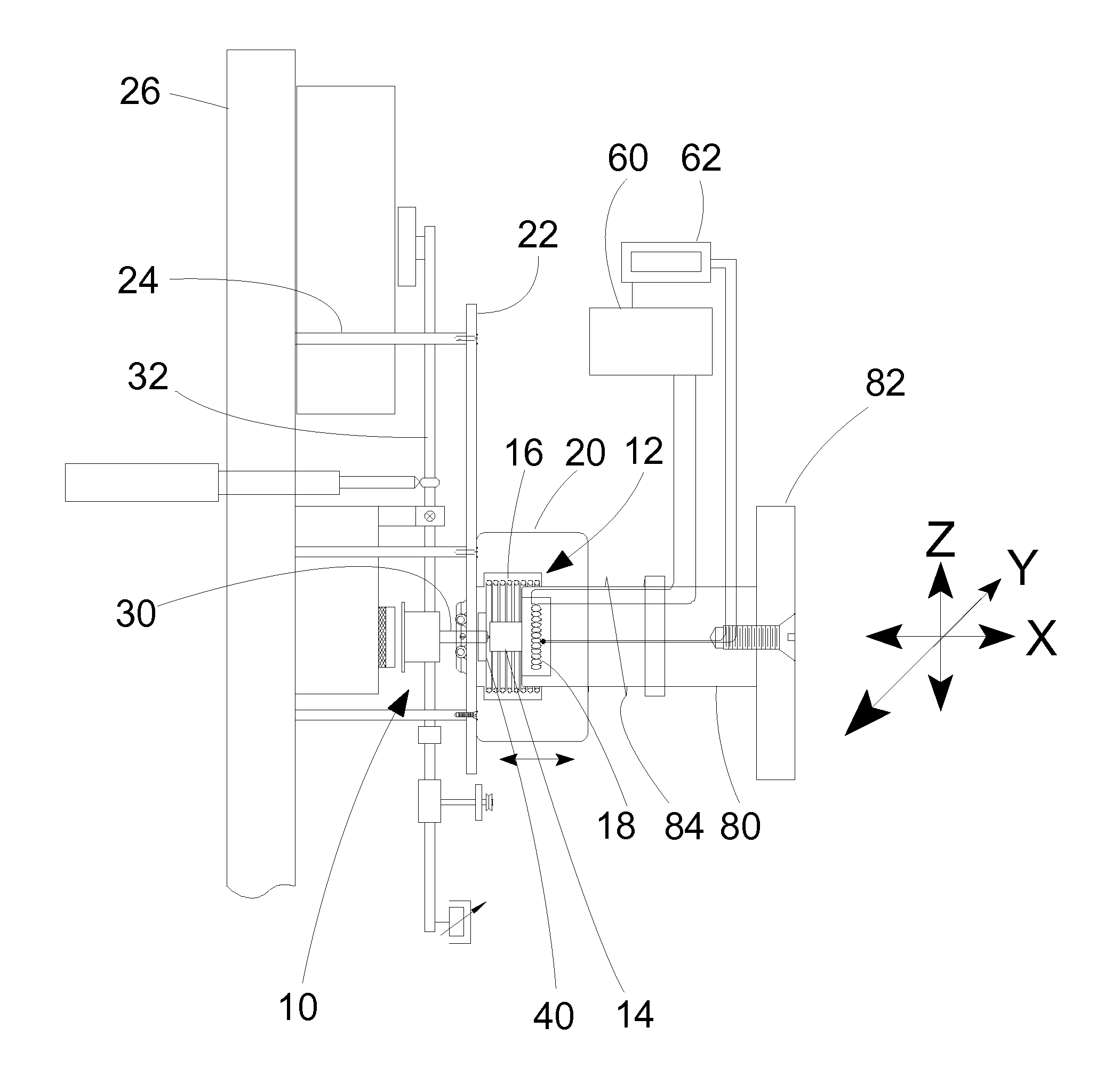
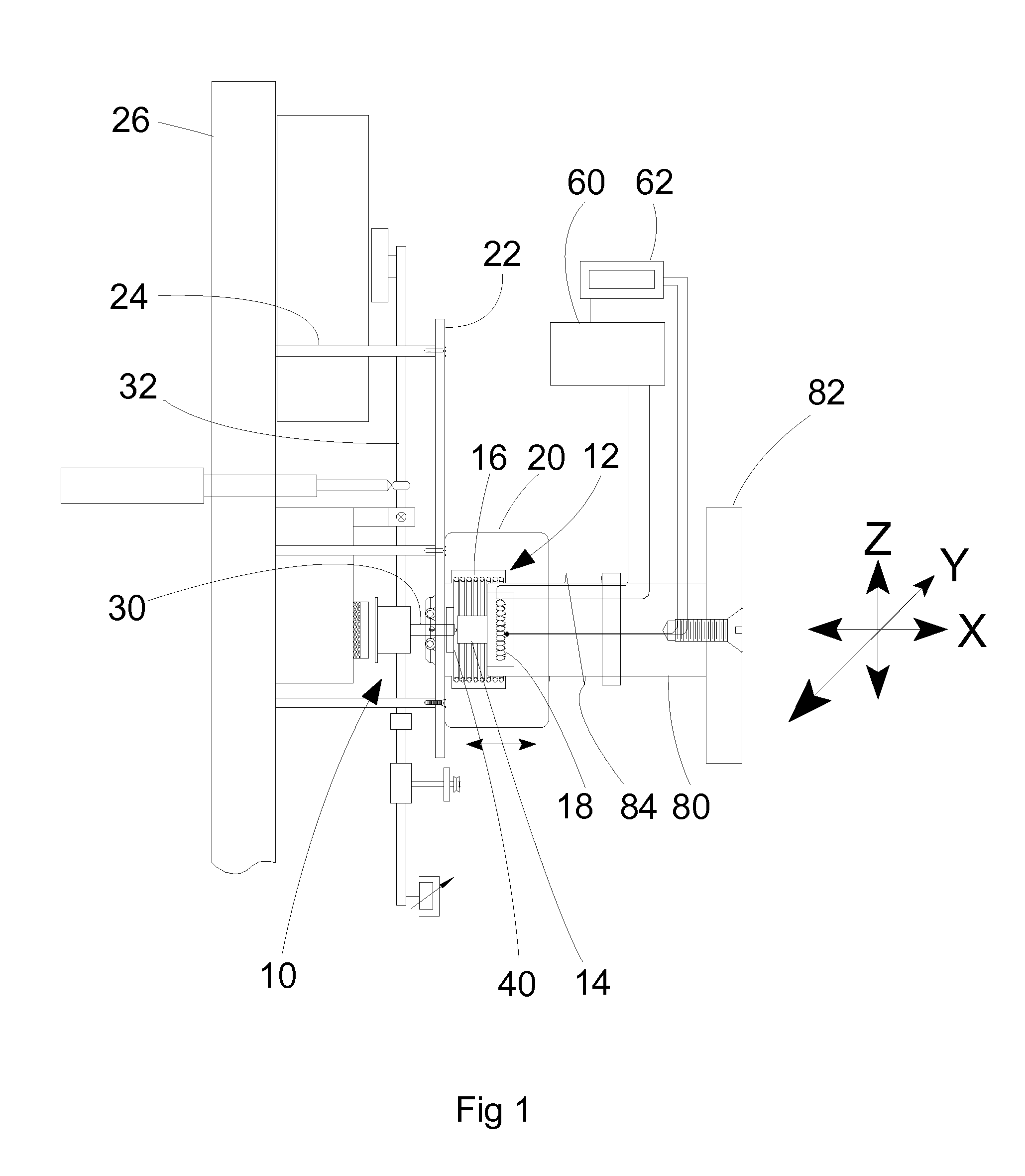
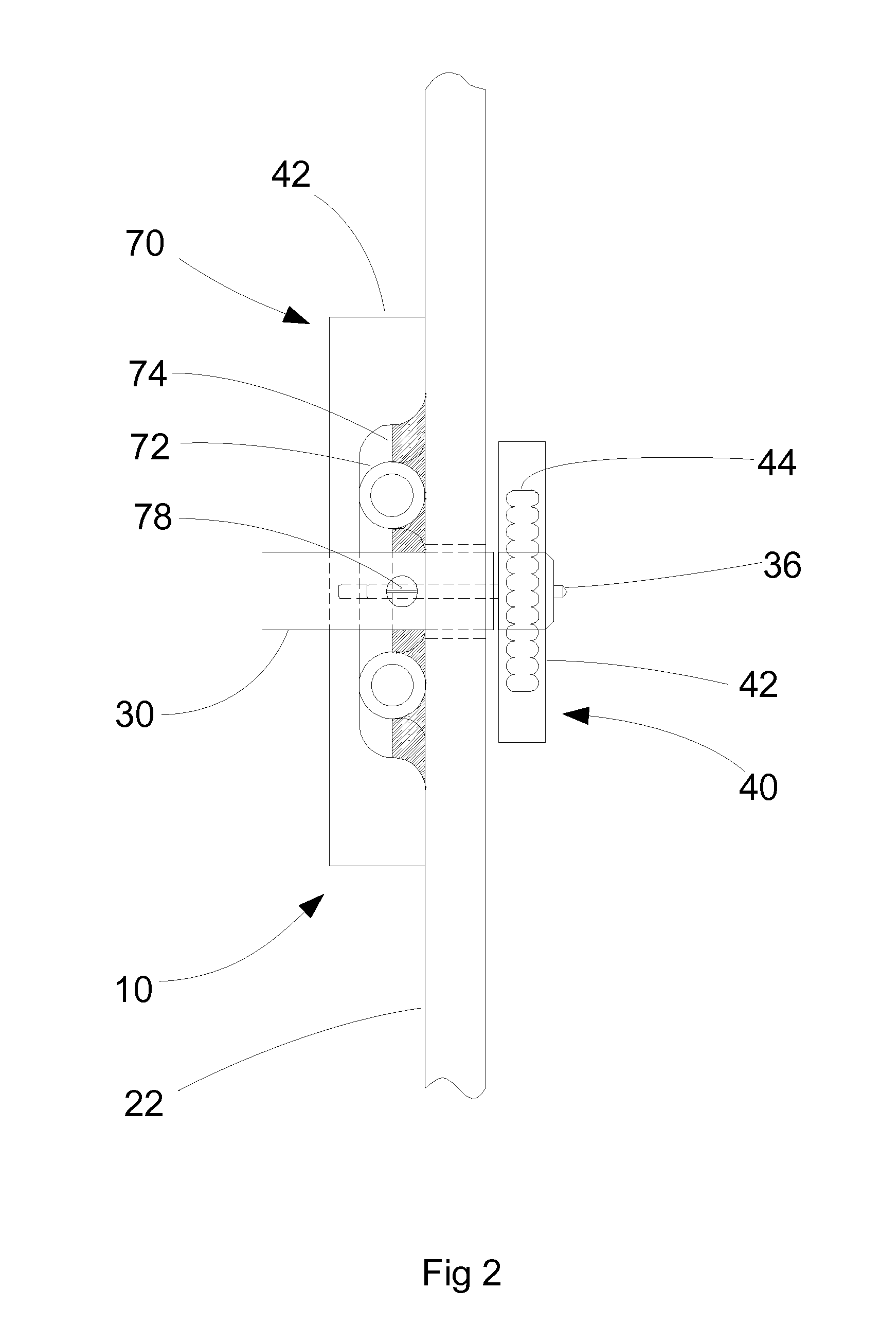
[0034]With reference to FIGS. 1 and 2, test apparatus embodying the invention comprises two main sub-assemblies: a pendulum that carries a probe assembly 10 and a sample carrier assembly 12 that carries a sample 14 to be tested on a support 80. The support 80 is connected to a mounting plate 82, which is a standard shape and size for connection with a conventional 3-axis stage. In this example, the sample is heated by electrically-operated resistive heating elements 16, 18. The carrier assembly 12 and the sample 14 are within a void formed within a ceramic, thermal enclosure 20 also carried on the support. The enclosure 20 can slide on the support 80 independently of the sample and the heating elements 16, 18 in a direction that is parallel to the motion of the carrier assembly 12.

[0035]In operation, the probe assembly is moved repeatedly with respect to a sample such that either the probe repeatedly impacts with the sample or such that the probe remains in contact with the sample a...


PUM

PropertyMeasurementUnit
temperatureaaaaaaaaaa
temperaturesaaaaaaaaaa
temperatureaaaaaaaaaa

Abstract

A method of controlling the temperature of a probe in materials testing apparatus, and apparatus operating by that method are disclosed. The apparatus includes heating elements that can by supplied with energy to apply heat to the probe. The method has a heating phase. In the heating phase, closed-loop temperature control is used to supply energy to the heating elements to heat the probe to a target temperature. When the probe has reached the target temperature, the average power that is being supplied to the heating elements is determined. Then, in a temperature maintenance phase, a continuous constant source of energy at a power that is substantially equal to the determined average power is supplied to the heating elements to maintain the probe at the target temperature.

Description

CROSS REFERENCE TO RELATED APPLICATION[0001]This Application is a national stage entry of PCT / GB2011 / 050331 filed Feb. 21, 2011, under the International Convention claiming priority over Great Britain Application No. 1003191.2 filed Feb. 25, 2010.TECHNICAL FIELD[0002]This invention relates to controlled heating in material testing apparatus. In particular, it relates to an assembly that is capable of maintaining a test probe and specimen at a constant, elevated temperature in apparatus for testing the surface and thin-film mechanical properties of materials on a small scale.BACKGROUND OF THE INVENTION[0003]The small-scale surface mechanical properties of materials are of importance to engineers because such properties can be of significance for the performance of an engineered component on a macroscopic scale. For example, where components move over one another in a machine, the rate and manner in which those components wear, and their resistance to fatigue and fracture, may be larg...

Claims


Application Information

Patent Timeline
Patent Type & Authority Applications(United States)
IPC IPC(8): G01N25/00
CPCB60Q9/008G01S2013/9375G01N25/00G01S2013/9385G01S2013/9378G01N3/42G01N3/54G01N2203/0222G05D23/1919G01S2013/93274G01S2013/93272G01S2013/93271G01N3/48
Inventor SMITH, JAMES FRANKPICKFORD, NICHOLAS
Owner MICRO MATERIALS LTD
Why Eureka
Try Eureka