

Method and device for monitoring and optimizing injection molding processes
a technology of injection molding and monitoring and optimization, applied in the direction of liquid/fluent solid measurement, volume/mass flow by dynamic fluid flow effect, material analysis using acoustic emission techniques, etc., can solve the problem of defect and other defects that are difficult to identify, defects or deficiencies may respectively occur, and defects and other defects are difficult to identify
- Summary
- Abstract
- Description
- Claims
- Application Information
AI Technical Summary
Benefits of technology
Problems solved by technology
Method used
Image

Examples
Embodiment Construction
[0054]The invention is initially described below with reference to an exemplary embodiment of an injection moulding process.
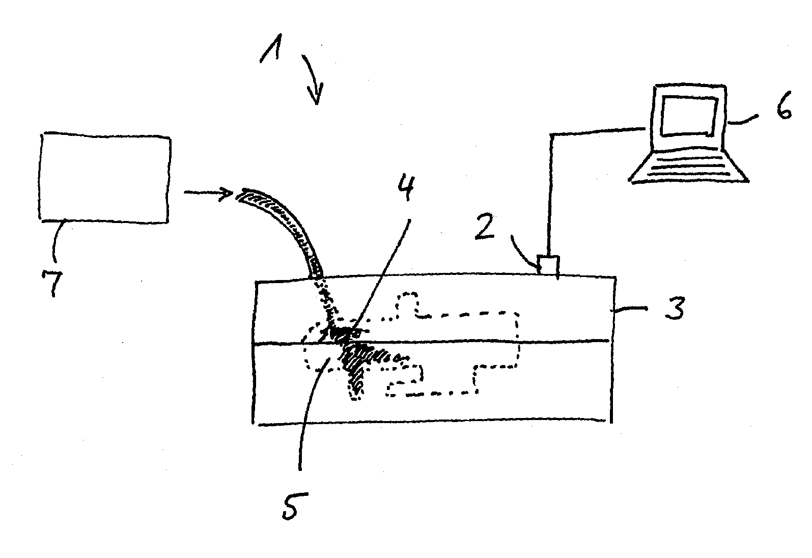
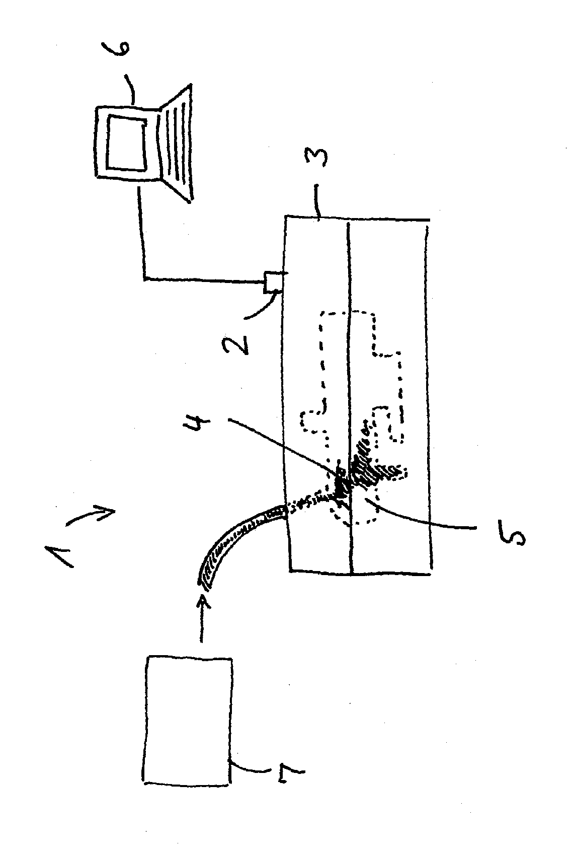
[0055]The device 1 for monitoring an injection moulding process illustrated in the figure comprises a sensor 2 for recording vibrations that is arranged, for example, on a tool 3, into which plastic 4 is injected under high pressure in order to mould a workpiece 5. The sensor 2 is connected to an analysis means 6 such as, e.g., a computer. The material that consists of plastic 4 in this case is supplied by a material feed device 7 that may consist of a container, an extruder, a feed screw, etc.
[0056]The sensor 2 preferably consists of a structure-borne sound sensor, e.g. a piezoelectric sensor, and preferably can not only record, but also emit structure-borne sound signals. The emission of structure-borne sound signals is particularly advantageous for the active monitoring of “quiet” flow processes because vibrations can be stimulated in this way. However, it i...
PUM
| Property | Measurement | Unit |
|---|---|---|
| frequency | aaaaa | aaaaa |
| pressure | aaaaa | aaaaa |
| frequencies | aaaaa | aaaaa |
Abstract
Description
Claims
Application Information