Hydraulic drive for a pressure booster

a technology of hydraulic drive and pressure booster, which is applied in the direction of valve details, operating means/releasing devices of valves, gas/liquid distribution and storage, etc., can solve problems such as material damage, and achieve the effects of reducing power consumption, increasing energy efficiency, and increasing the service life of the apparatus

Active Publication Date: 2013-07-04
BFT
View PDF19 Cites 20 Cited by
  • Summary
  • Abstract
  • Description
  • Claims
  • Application Information

AI Technical Summary

Benefits of technology

[0011]In accordance with the demands on technical progress in the sector of high-pressure apparatuses, i.e., the safety of the plant control, the minimization of the pressure surges and thus the minimization of the material overloads of components in the high pressure section, the increase in the service life of the apparatus, the incr...

Problems solved by technology

Although pressure relief valves are provided throughout therein for sudden interruptions of the flow of the...

Method used


Image

  • Hydraulic drive for a pressure booster
  • Hydraulic drive for a pressure booster

Examples


Embodiment Construction

[0033]The particulars shown herein are by way of example and for purposes of illustrative discussion of the embodiments of the present invention only and are presented in the cause of providing what is believed to be the most useful and readily understood description of the principles and conceptual aspects of the present invention. In this regard, no attempt is made to show structural details of the present invention in more detail than is necessary for the fundamental understanding of the present invention, the description taken with the drawings making apparent to those skilled in the art how the several forms of the present invention may be embodied in practice.

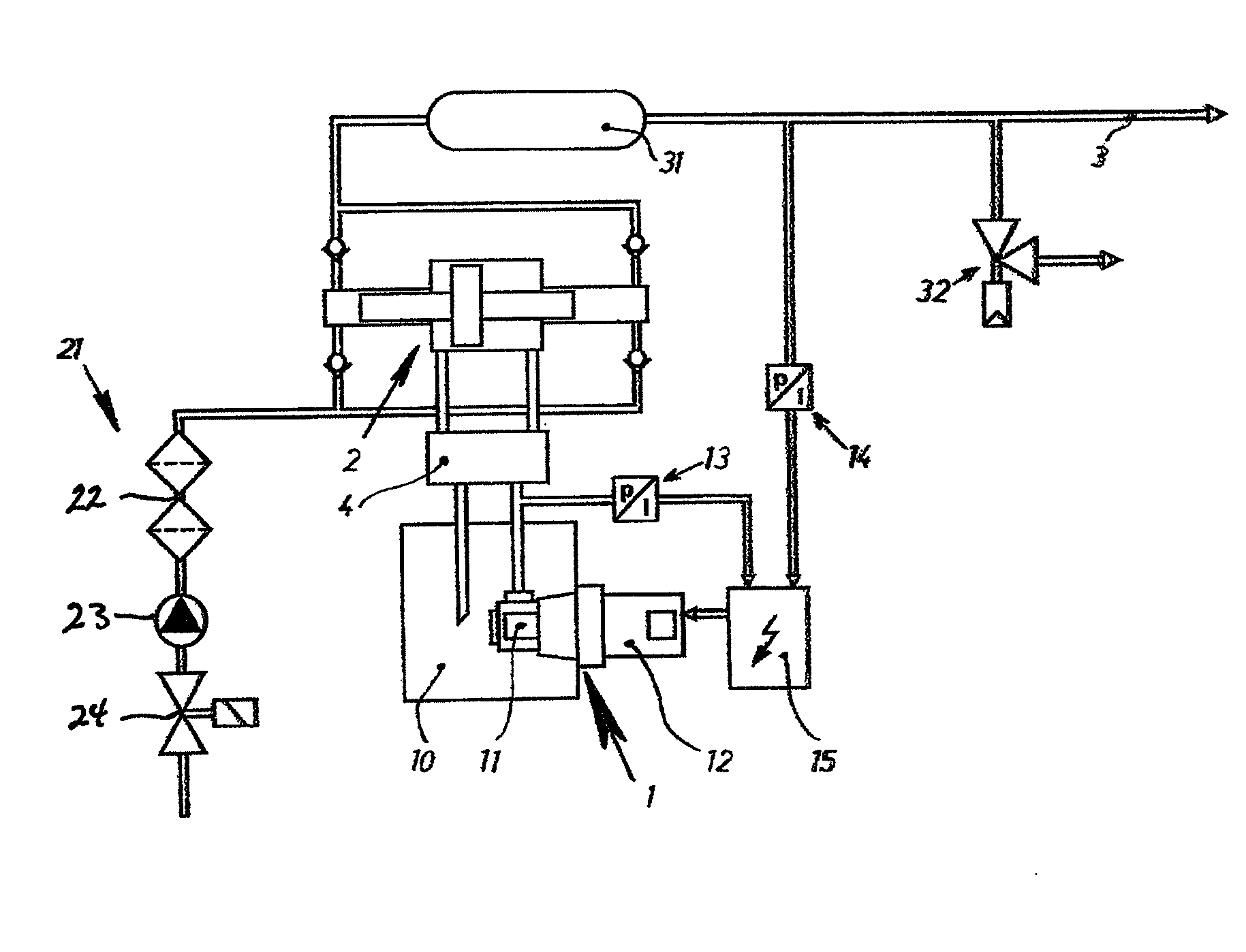
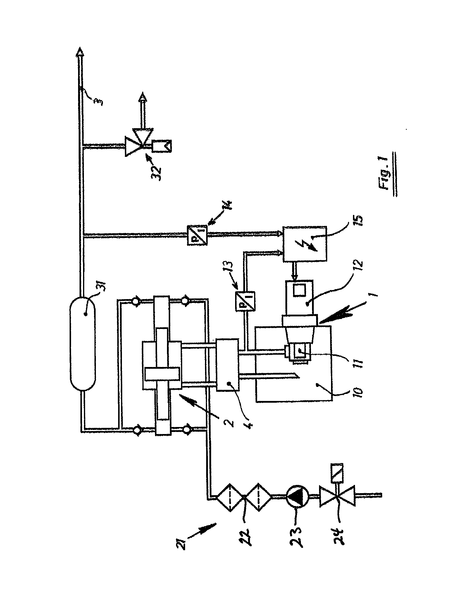
[0034]FIG. 1 diagrammatically shows a high pressure apparatus with a conveyor line 3, a pulsation damper 31 and a pressure relief valve 32 on the outlet side.

[0035]A pressure booster 2 can be supplied with high-pressure fluid via series units 21, such as, for example, low pressure filters 22, booster pump 23, and shut-off...


PUM


Abstract

Hydraulic drive and method for driving a pressure booster of a high-pressure apparatus. The hydraulic drive includes a pressure medium pump having one of a constant displacement pump and a pump conveying a constant volume per revolution, a servo motor coupled to drive the pump, and a controller structured to at least one of electrically control, regulate and switch the servo motor, which is arranged on at least one of a low pressure side and a high pressure side of the pressure booster.

Description

CROSS-REFERENCE TO RELATED APPLICATIONS[0001]The present application claims priority under 35 U.S.C. §119 of Austrian Patent Application No. A 1909 / 2011 filed Dec. 30, 2011, the disclosure of which is expressly incorporated by reference herein in its entirety.BACKGROUND OF THE INVENTION[0002]1. Field of the Invention[0003]The invention relates to a hydraulic drive with a quantity control and / or pressure control for a pressure booster of a high-pressure apparatus, comprising essentially a motor drive with a pump for a pressure medium as well as a control.[0004]2. Discussion of Background Information[0005]Modern high-pressure apparatuses operate with pressures of up to 10,000 bar and more and make extremely high mechanical demands on the materials of the apparatus components, which often lie in the limit range of the high-strength alloys with respect to mechanical tensile strength and alternate strength. Although pressure relief valves are provided throughout therein for sudden interr...

Claims


Application Information

Patent Timeline
IPC IPC(8): F16K31/12
CPCF04B17/03F04B2207/02F04B49/06F04B49/022F04B9/113Y10T137/0391Y10T137/7769
Inventor TRIEB, FRANZSTUEHLINGER, RENEMODERER, RENE
Owner BFT
Why Eureka
Try Eureka