Supercharge Your Innovation With Domain-Expert AI Agents!

Apparatus and Methods for Controlling a Laser Output and Improving Laser Safety Using a Proximity Sensor

Active Publication Date: 2013-07-04
MAGNOLIA SOURCE CAYMAN
View PDF3 Cites 0 Cited by
  • Summary
  • Abstract
  • Description
  • Claims
  • Application Information

AI Technical Summary

Benefits of technology

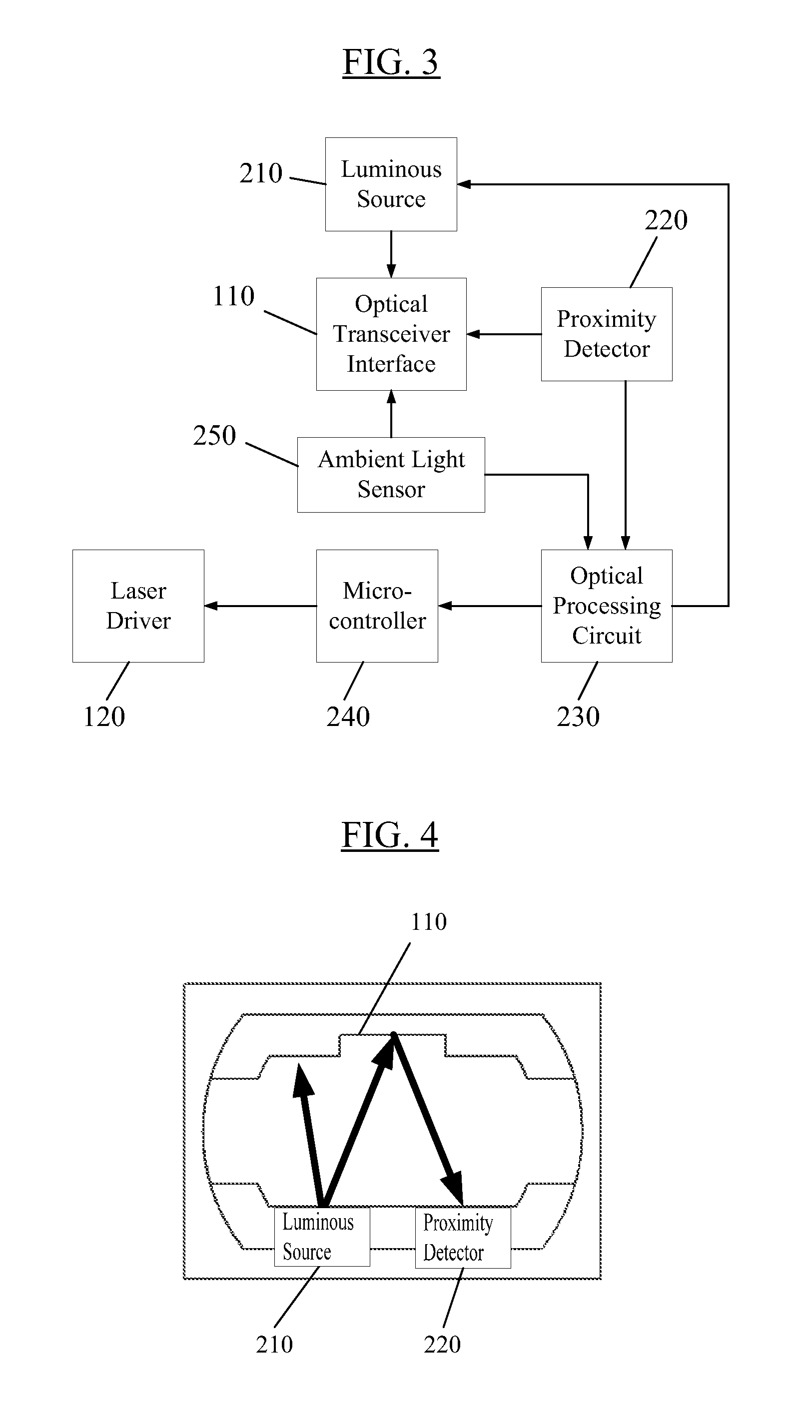
The present invention is a laser output control method and device designed to prevent harmful exposure to strong laser light or radiation when a fiber is not inserted into a transceiver. The invention achieves this by restricting the laser output activity and energy to enhance the security of laser usage and protection of the human body. The invention has advantages in detecting the reflection intensity of the luminous beam from the luminous source, utilizing the microcontroller to determine whether a fiber is connected to the optical interface, and restricting the laser output and total laser output energy to prevent harmful exposure of human eyes.

Problems solved by technology

Currently, the total output of a laser is conventionally restricted by the handshake mode (e.g., the process of one device connecting with another device) between optical transceivers.
However, all of the various handshake modes or protocols have one fundamental issue, which is that the architecture can be realized generally only when the optical transceivers at the transmitting end and the receiving end are from the same manufacturer.
However, with regard to the terminals in the handshake, this property is not described in any applicable multisource agreement (MSA).
Thus, compatibility issues caused by handshake mechanisms exist in real world applications.

Method used


Image

  • Apparatus and Methods for Controlling a Laser Output and Improving Laser Safety Using a Proximity Sensor
  • Apparatus and Methods for Controlling a Laser Output and Improving Laser Safety Using a Proximity Sensor
  • Apparatus and Methods for Controlling a Laser Output and Improving Laser Safety Using a Proximity Sensor

Examples


Embodiment Construction

[0023]The present invention will become readily apparent from the detailed description of embodiments and drawings below.

[0024]Reference will now be made in detail to various embodiments of the invention, examples of which are illustrated in the accompanying drawings. The technical proposal(s) of embodiments of the present invention will be fully and clearly described in conjunction with the drawings. In the following embodiments, it will be understood that the descriptions are not intended to limit the invention. Based on the described embodiments of the present invention, other embodiments obtained by one skilled in the art without creative contribution are considered in the scope of legal protection given to the present invention. While the invention will be described in conjunction with the following embodiments, it will be understood that the descriptions are not intended to limit the invention to these embodiments. On the contrary, the invention is intended to cover alternativ...


PUM


Abstract

A laser output control method and a laser output control device, including a luminous source in the optical interface of an optical transceiver, a proximity detector configured to detect and capture reflection intensity of a luminous beam from the luminous source, an optical processing circuit electrically connected to the proximity detector and configured to receive and process the reflection intensity, and a microcontroller configured to capture parametric information of the reflection intensity, are disclosed. The microcontroller is also electrically connected to a laser driver, to receive parametric information of the optical processing circuit and to regulate the laser and / or laser driver activity based on the parametric information. The laser output control device may effectively restrict the laser output activity and the total laser output energy, which may prevent exposing human eyes to relatively strong laser energy and enhance the security of laser usage and protection for the human body.

Description

CROSS-REFERENCE TO RELATED APPLICATION[0001]This application claims the benefit of Chinese Patent Application No. 201110451785.0, which was filed on Dec. 29, 2011, and is incorporated by reference as if fully set forth herein.FIELD OF THE INVENTION[0002]The present invention generally relates to the field of laser control, in particular to a method and device for controlling a laser output.DISCUSSION OF THE BACKGROUND[0003]As is well-known, when a laser is emitted from one optical transceiver and transmitted to another optical transceiver via a properly connected fiber, a completed communication mechanism and channel exists so that emitted laser can be conveyed properly. As is required by international laser safety standards, in order to prevent exposing the naked eye to laser leakage, the total output energy of the laser when a fiber is not connected needs to be efficiently regulated. Thus, when the fiber is connected to the optical transceiver interfaces on both sides, the laser b...

Claims


Application Information

Patent Timeline
IPC IPC(8): H01L31/14G01J5/10H01L31/16
CPCH01S5/06825H01L31/16H04B10/564H04B10/503
Inventor CHANG, YUNG CHENGCHOU, E. MINJAN, YU HENG
Owner MAGNOLIA SOURCE CAYMAN
Features
  • R&D
  • Intellectual Property
  • Life Sciences
  • Materials
  • Tech Scout
  • Unparalleled Data Quality
  • Higher Quality Content
  • 60% Fewer Hallucinations
Learn More