Method and device for controlling a video projector in a video projection system comprising multiple video projectors

a video projection system and video projector technology, applied in the field of video projection, can solve the problems of destroying the calibrated image partitioning and the impression of continuity, and achieve the effect of minimizing the relative measurement errors introduced during calibration and improving calibration precision

Inactive Publication Date: 2013-07-04
CANON KK
View PDF18 Cites 36 Cited by
  • Summary
  • Abstract
  • Description
  • Claims
  • Application Information

AI Technical Summary

Benefits of technology

[0022]According to a particular embodiment, the at least one first and second calibration parameters comprise positions of predetermined points of sub-images projected by video projectors of a set of the video projectors, the set of video projectors comprising the at least one video projector, and the at least one display parameter relates to a projection position of a sub-image to be projected by the at least one video projector. Such predetermined points can be corners that are easily identified. It is noted here that the calibration precision increases when two or more calibration points are used, even in the presence of fabrication or installation tolerances.
[0025]The step of computing at least one display parameter may comprise the two determining steps of determining at least one sub-image that is to be projected by the at least one video projector and determining the projection position of the at least one sub-image that is to be projected by the at least one video projector, the two determining steps being based upon the at least one second calibration parameter. The method according to the invention is thus easily implemented.
[0028]According to a particular embodiment, the first predetermined focal length of the video projectors is the minimum focal length of the projectors' zoom lenses. It is noted that a minimum focal length means a maximum image size. Hence, the relative measurement errors introduced during calibration are minimized.
[0029]Still according to a particular embodiment, the at least one first calibration parameter is determined for at least two distinct calibration focal lengths. The at least two distinct calibration focal lengths may comprise the minimum and maximum focal lengths of the projectors' zoom lenses, interpolation from the two extreme focal lengths enabling better calibration precision for an intermediate focal length.
[0043]According to a particular embodiment, the at least one microprocessor is further configured for carrying out a step of up-scaling a part of an image to be projected by the video projection system, interpolating points of the part of the image, and down-scaling the part of the image, when carrying out the step of calculating at least one sub-image to be projected by the at least one video projector, so as to correct geometric distortions.

Problems solved by technology

However, it has been observed that actuating the optical zooms of video projectors belonging to such a video projection system changes the relative width of the overlapped zones, and hence destroys the calibrated image partitioning and the impression of continuity.

Method used


Image

  • Method and device for controlling a video projector in a video projection system comprising multiple video projectors
  • Method and device for controlling a video projector in a video projection system comprising multiple video projectors
  • Method and device for controlling a video projector in a video projection system comprising multiple video projectors

Examples


Embodiment Construction

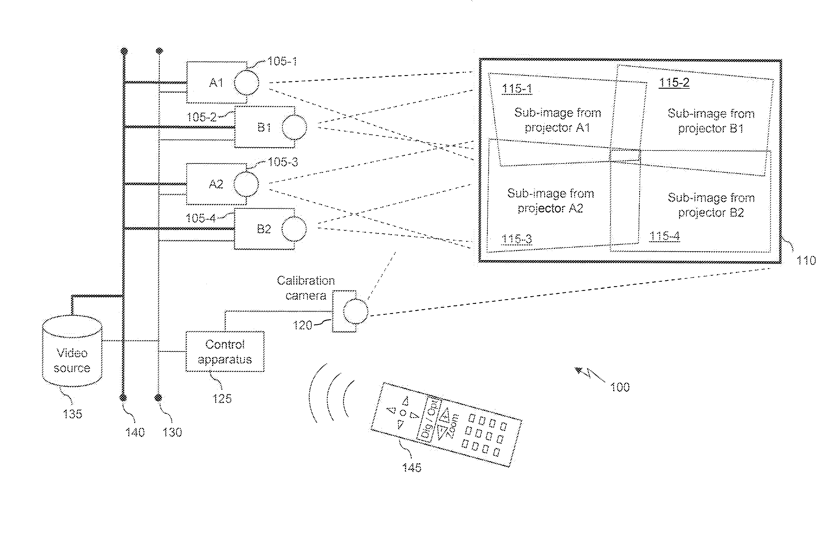
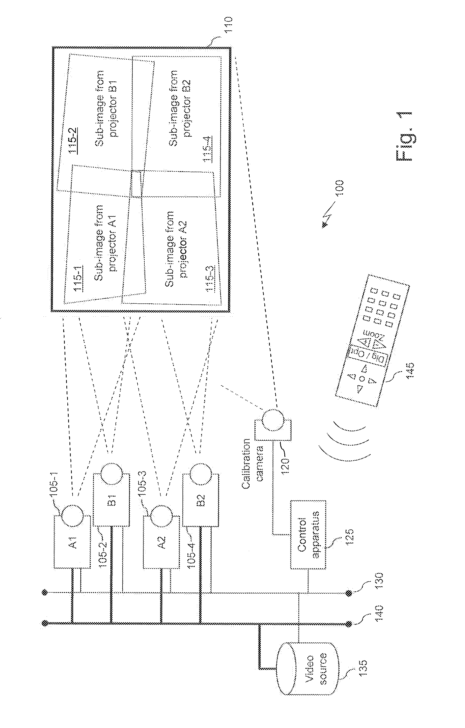
[0057]For the sake of clarity below, an image or a video image refers to an image displayed on a video screen by a video system comprising one or several video projectors (also referred to as projectors) while a sub-image is an image projected by a single projector of a video system (comprising one or several projectors).

[0058]According to the invention, the control of one video projector or a group of video projectors in a video projection system comprising several video projectors is performed in two stages, one relating to the initialization of the system and another one being directed to zoom commands during video projection.

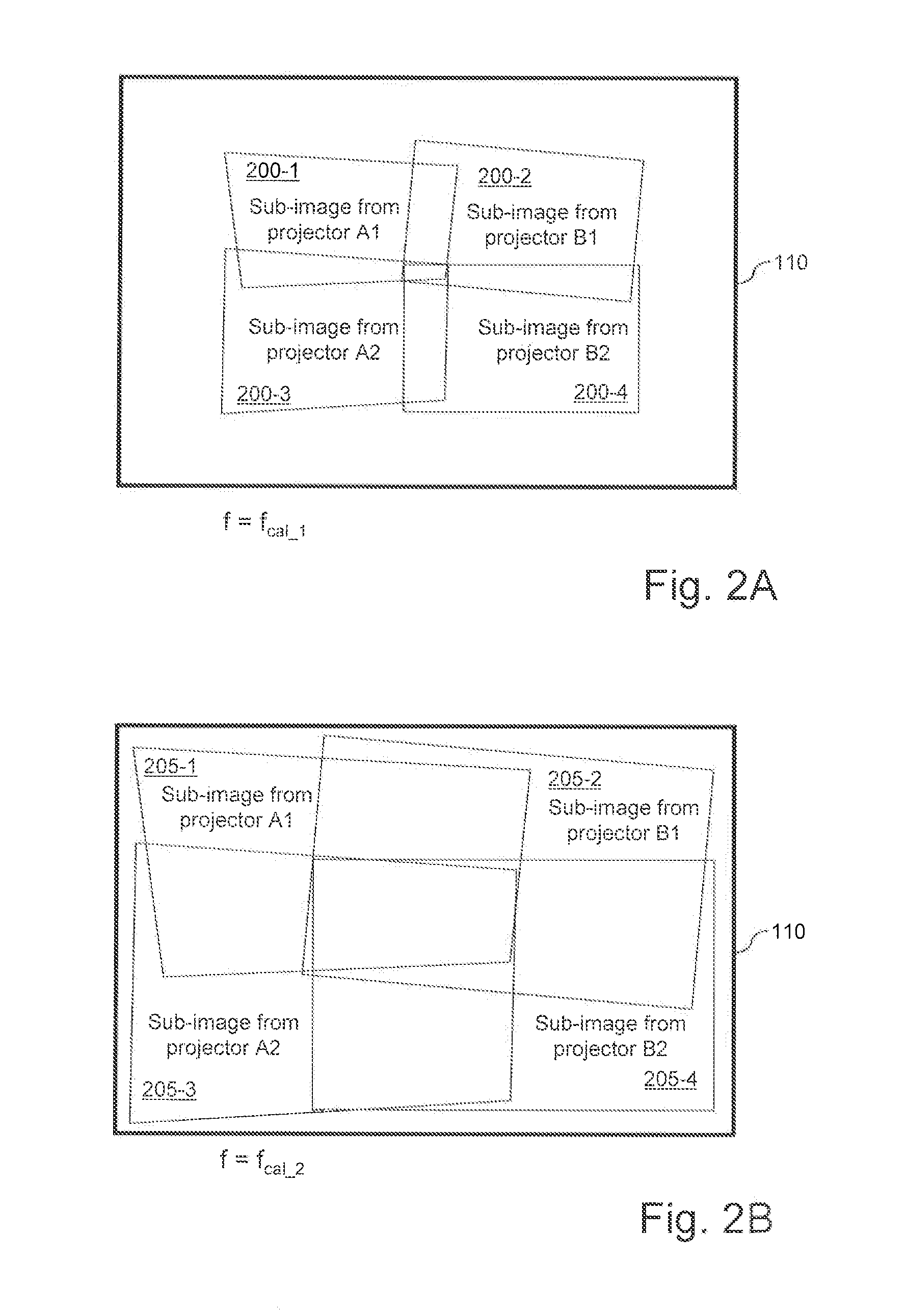
[0059]Generally speaking, the initialization stage according to the invention preferably comprises the following steps:[0060]adjusting parameters of all projectors to a given focal length, preferably the minimum focal length that corresponds to the maximum sub-image size for a given distance between projectors and screen;[0061]determining the coordinates of ...


PUM


Abstract

Controlling at least one video projector of a video projection system comprising multiple video projectors having a modifiable focal length and adapted to project sub-images. After determining a first calibration parameter associated with a first predetermined focal length of the video projectors, a second calibration parameter corresponding to a second predetermined focal length of the video projectors is computed, the second calibration parameter computed as a function of the first calibration parameter and the second predetermined focal length different from the first one. A display parameter is computed for a video projector, the display parameter being computed as a function of second calibration parameter, and a sub-image to be projected by the video projector is calculated according to the computed display parameter. Necessary display parameters are determined during an initial calibration step and used during a projection session whenever the user issues an “optical zoom” command, without repeating the calibration.

Description

CROSS-REFERENCE TO RELATED APPLICATION[0001]This application claims the benefit under 35 U.S.C. §119(a)-(d) of United Kingdom Patent Application No. 1122084.5, filed on Dec. 22, 2011 and entitled “Method and device for controlling a video projector in a video projection system comprising multiple video projectors”. The above cited patent application is incorporated herein by reference in its entirety.FIELD OF THE INVENTION[0002]The present invention relates generally to video projection and more specifically to a method and a device for controlling a video projector apparatus or a group of aggregated video projector apparatuses.BACKGROUND OF THE INVENTION[0003]Videos are generally projected as sequences of images on a video screen by a video projection system composed of a single video projector or multiple video projectors generating adjacent, partially overlapping sub-images. Projected images can be of a standard definition or of a high definition (HD), offering high image quality...

Claims


Application Information

Patent Timeline
Patent Type & Authority Applications(United States)
IPC IPC(8): H04N9/31
CPCG03B33/10H04N9/3185G03B21/147H04N9/3188H04N9/3194H04N9/3147
Inventor TANNHAUSER, FALKROUSSEAU, PASCAL
Owner CANON KK
Why Eureka
Try Eureka