Transmission circuit, reception circuit, transmission method, reception method, communication system and communication method therefor

Inactive Publication Date: 2013-07-04
PANASONIC CORP
View PDF8 Cites 16 Cited by
  • Summary
  • Abstract
  • Description
  • Claims
  • Application Information

AI Technical Summary

Benefits of technology

[0019]The present invention achieves early establishment of symbol synchronization while supp

Problems solved by technology

Nevertheless, a strict restriction is still posed on the

Method used


Image

  • Transmission circuit, reception circuit, transmission method, reception method, communication system and communication method therefor
  • Transmission circuit, reception circuit, transmission method, reception method, communication system and communication method therefor
  • Transmission circuit, reception circuit, transmission method, reception method, communication system and communication method therefor

Examples


Example

[0037]The following describes a communication system as an embodiment of the present invention with reference to the drawings.

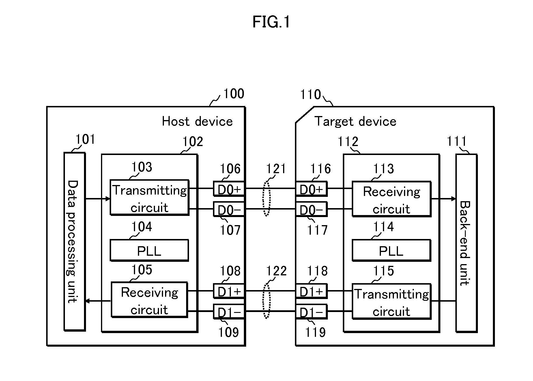
[0038]FIG. 1 is a block diagram illustrating an example of the structure of the communication system.

[0039]As illustrated in FIG. 1, the communication system includes a host device 100 and a target device 110. The host device 100 and the target device 110 are connected to each other via serial channels 121 and 122.

[0040]Each of the serial channels 121 and 122 is a pair of signal lines used for data transmission in differential signaling. The serial channel 121 includes signal lines D0+ and D0−, and is used to perform data transmission from the host device 100 to the target device 110. Similarly, the serial channel 122 includes signal lines D1+ and D1−, and is used to perform data transmission from the target device 110 to the host device 100. In a case where a differential signal is transmitted, antiphase signals relative to signals passing though the signal ...


PUM


Abstract

In transmission of channel-coded serial data, early establishment of symbol synchronization between a transmitter and a receiver is achieved while reducing coding loss in transmission of valid data. In an idle period for not transmitting the valid data, a transmitting circuit selects first channel coding (e.g. 8B/10B coding) enabling early establishment of synchronization and transmits a synchronization symbol encoded using the first channel coding. In response to this, a receiving circuit establishes and maintains symbol synchronization. When the valid data is transmitted, the transmitting circuit transmits a symbol indicating a packet start position, selects second channel coding (e.g. 64B/66B coding) having less coding loss than the first channel coding, and transmits the valid data encoded using the second channel coding. Upon reception of the symbol indicating the packet start position, the receiving circuit switches to reception using the second channel coding and receives the valid data.

Description

TECHNICAL FIELD[0001]The present invention relates to a transmitting circuit, a receiving circuit, a transmission method, a reception method, a communication system, and a communication method for the communication system for performing serial transmission using channel coding to carry out communications, and, in particular, to technology for achieving early establishment of synchronization and reduction of coding loss.BACKGROUND ART[0002]With recent development in technology for miniaturizing semiconductor devices and accelerating the processing speed thereof, the amount of data communicated between devices or LSIs (Large Scale Integrations) provided in the devices is increasing more than ever. With increasing amount of communicated data, it is desirable that the number of terminals (pads) required for data communications also increase. Nevertheless, a strict restriction is still posed on the number of terminals in an LSI, which affects the costs. For the purpose of achieving high-...

Claims


Application Information

Patent Timeline
IPC IPC(8): H04L7/10
CPCH04L25/4908H04L7/10H04L1/08H04L1/0083H04L1/0057H04W56/00
Inventor NISHIOKA, SHINICHIRO
Owner PANASONIC CORP
Why Eureka
Try Eureka