Floor tool for a vacuum cleaning appliance

a vacuum cleaning and floor tool technology, applied in the field of floor tools, can solve the problems of affecting the pick-up performance of such tools on hard floors, less accomplished at removing other forms of dirt, etc., and achieve the effect of improving the debris pickup performance of the floor tool and low profil

Inactive Publication Date: 2013-07-11
DYSON TECH LTD
View PDF1 Cites 10 Cited by
  • Summary
  • Abstract
  • Description
  • Claims
  • Application Information

AI Technical Summary

Benefits of technology

[0022]Beneficially, the side-by-side location of the two suction chambers improves the debris pickup performance of the floor tool across its entire width.
[0023]To enable the main body to be widely maneuverable over a surface, the conduit preferably comprises a front section and a rear section. The front section is pivotably connected to the main body for movement about a first axis to allow the rear section of the conduit to be raised and lowered relative to the main body, which allows the main body to be maneuvered easily beneath furniture, and into gaps between furniture and walls as required. The range of articulation of the sections of the conduit about the first and second axes preferably enables the main body to be oriented both substantially perpendicular to a wand used to manoeuvre the tool over a floor surface, and substantially parallel to the wand.
[0024]Whilst the front section is pivotable to the main body in a substantially vertical plane, the rear section is pivotably connected to the front section for movement relative thereto about a second axis which is spaced from the first axis. This allows the rear section to be angled relative to the front section to assist in the pushing, or pulling, of the main body over a surface, such as a floor surface, in a variety of orientations of the main body relative to, for example, a wand connected to the rear section of the conduit. The pivoting connection between the front section and the rear section enables the rear section to be connected to the front section so that it is located at least partially beneath the front section. This can allow the tool to have a low profile when the front section of the conduit is in its lowered position.

Problems solved by technology

Although floor tools are adept at removing loose dirt and debris from a floor surface, they are less accomplished at removing other forms of dirt, for example stains, which may be left behind from liquid that is spilt on a hard floor covering.
Although such combined mop and suction floor tools have their advantages, the pick-up performance of such tools on hard floors tends to be compromised.

Method used


Image

  • Floor tool for a vacuum cleaning appliance
  • Floor tool for a vacuum cleaning appliance
  • Floor tool for a vacuum cleaning appliance

Examples


Embodiment Construction

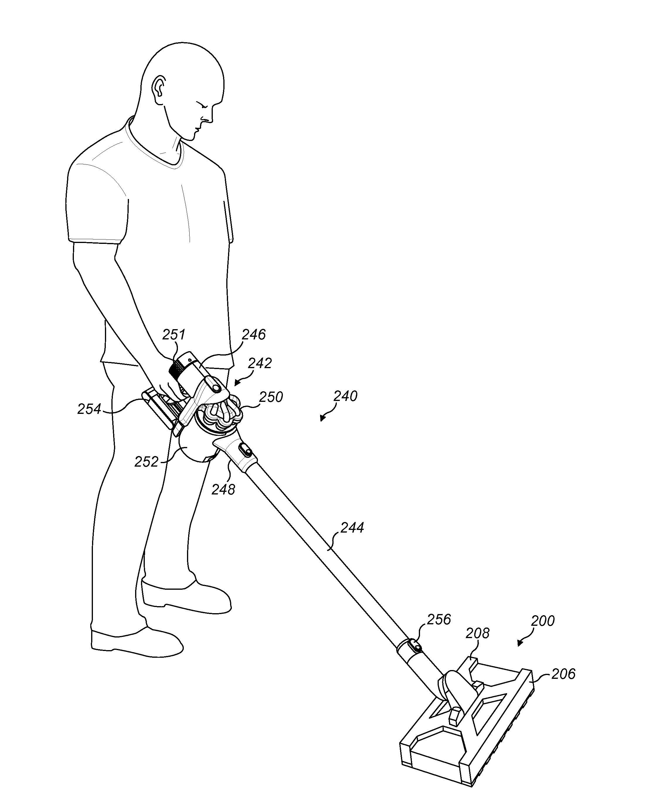
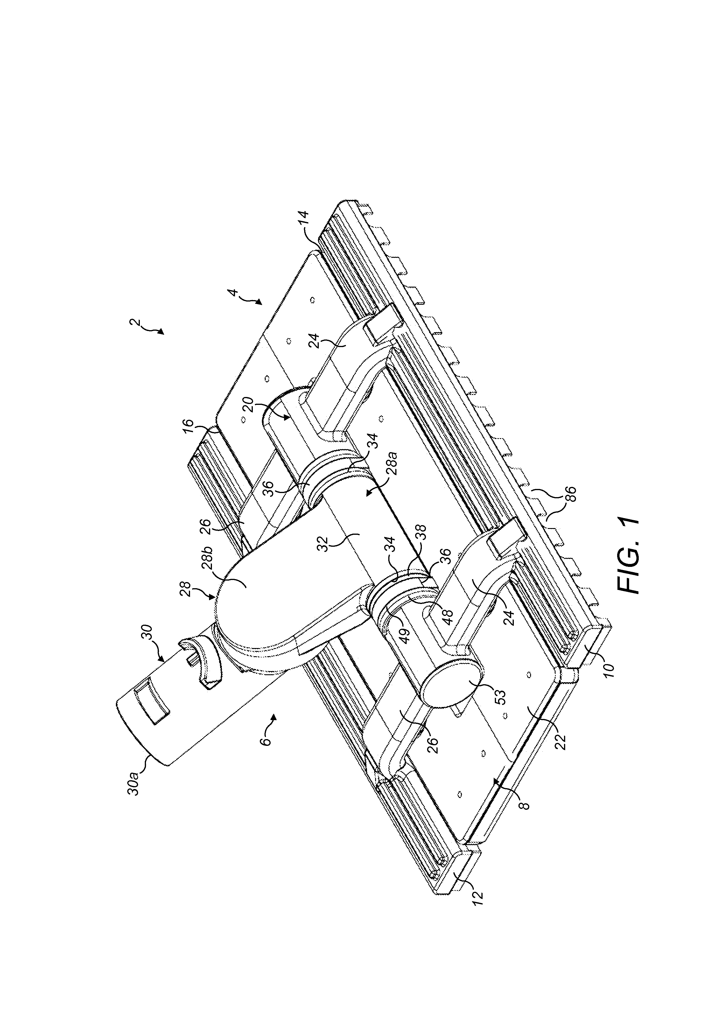
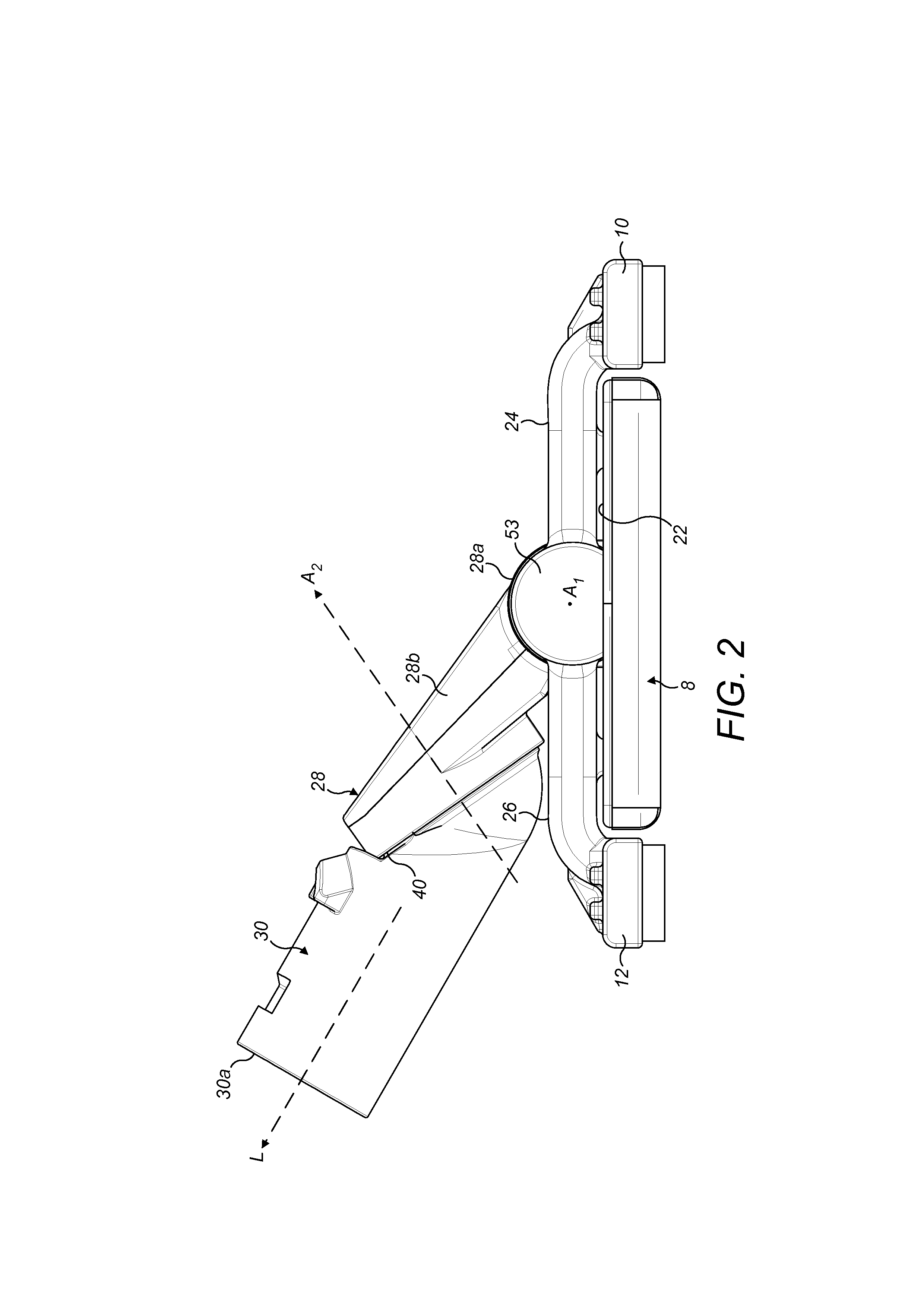
[0047]With reference in general to FIGS. 1 to 6, a floor tool 2 comprises a main body 4 and a conduit 6 associated with the main body 4 which serves to connect the floor tool 2 to a wand of a vacuum cleaner (not shown) and enables a user to manoeuvre the floor tool 2 across a surface to be cleaned.

[0048]The main body 4 comprises a generally oblong support member 8 on which can be carried a sheet-like cleaning element (shown in FIGS. 4 and 5), and first and second suction nozzles 10, 12 arranged adjacent respective long edges 14, 16 of the support member 8. Each of the suction nozzles 10, 12 is pivotably associated with an air manifold 20 that is mounted to an upper surface 22 of the support member 8. In the figures, the floor tool 2 is oriented such that its ‘front’ is facing towards the right hand side of the drawing. Therefore, the first and second suction nozzles 10, 12 can be considered to be a front suction nozzle 10 and a rear suction nozzle 12, respectively, and shall be refe...


PUM


Abstract

A floor tool for a vacuum cleaning appliance, comprising a main body connected to a conduit, the main body comprising, a supporting member adapted to support a cleaning element and a suction nozzle adjacent an edge of the supporting member, wherein the suction nozzle defines a suction chamber, and wherein the suction chamber includes a first fluid outlet and a second fluid outlet in communication with the conduit.

Description

REFERENCE TO RELATED APPLICATIONS[0001]This application claims the priority of United Kingdom Application No. 1200174.9, filed Jan. 6, 2012, and United Kingdom Application No. 1206545.4, filed Apr. 13, 2012, the entire contents of which are incorporated herein by reference.FIELD OF THE INVENTION[0002]The present invention relates to a floor tool for a vacuum cleaning appliance.BACKGROUND OF THE INVENTION[0003]Vacuum cleaners are generally supplied with a range of tools for dealing with different cleaning tasks. For example, such a tool may be a general purpose floor tool for on-the-floor cleaning of both hard and textile surface coverings. Typically, a floor tool comprises a main body which engages with a floor surface. The main body has a lower surface comprising a suction opening through which dirt and dust may be drawn into the floor tool due to a suction force generated by a vacuum cleaner to which the tool is attached. Although floor tools are adept at removing loose dirt and d...

Claims


Application Information

Patent Timeline
Patent Type & Authority Applications(United States)
IPC IPC(8): A47L9/02
CPCA47L9/02A47L9/0686A47L9/0613A47L13/20A47L9/04A47L9/0461A47L9/06A47L9/00
Inventor GUDER, CHRISTIANWILLS, ANDREW JAMES
Owner DYSON TECH LTD
Why Eureka
Try Eureka