Pipe press-connecting apparatus

a technology of pipe fittings and clamping devices, which is applied in the direction of metal working equipment, metal-working hand tools, metal-working tools, etc., can solve the problems of inability to smoothly perform pipe compression, unfavorable pipe compression, and damage to the compression tool itself, so as to increase the compression force and work convenience, prevent the deformation of the pipe oval

Inactive Publication Date: 2013-07-11
KIM KWANG - CHAN +1
View PDF9 Cites 9 Cited by
  • Summary
  • Abstract
  • Description
  • Claims
  • Application Information

AI Technical Summary

Benefits of technology

[0020]According to a pipe fitting and clamping apparatus proposed by the present invention, since the pivot blocks are connected to both of the left and right ends of the fixed block to compress the pipes using the principle of the lever, the compressing force can be increased by only a small force during the compressing work to increase work convenience.
[0021]In addition, since the plurality of inserts slide along the first and second insert guides to surround the entire circumference of the pipes and apply a uniform pressure during rotation of the pivot blocks, the pipes can be compressed in a perfect circle shape.
[0022]Further, since the entire circumference of the pipes can be uniformly pressed to be fitted and can prevent oval deformation of the pipes, a defect such as leakage from the connected pipes can be prevented, and durability can be increased, extending an exchange period of the connected pipes.

Problems solved by technology

In addition, since the pipes are compressed using the high pressure hydraulic cylinder, the compressing tool itself may be damaged.
In order to prevent the damage, when the thickness and weight of the compressing tool are increased, a working process may become uneasy due to the increased weight.
However, in the compressing tool disclosed in Korean Patent Registration No. 10-0762293, the pipe compressing cannot be smoothly performed due to a chain slack phenomenon during a process of compressing the pipes through application of the high pressure, and the compressing section cannot have a perfect circle.

Method used


Image

  • Pipe press-connecting apparatus
  • Pipe press-connecting apparatus
  • Pipe press-connecting apparatus

Examples


Embodiment Construction

[0031]Reference will now be made in detail to a pipe fitting and clamping apparatus of the embodiments of the present invention, examples of which are illustrated in the accompanying drawings.

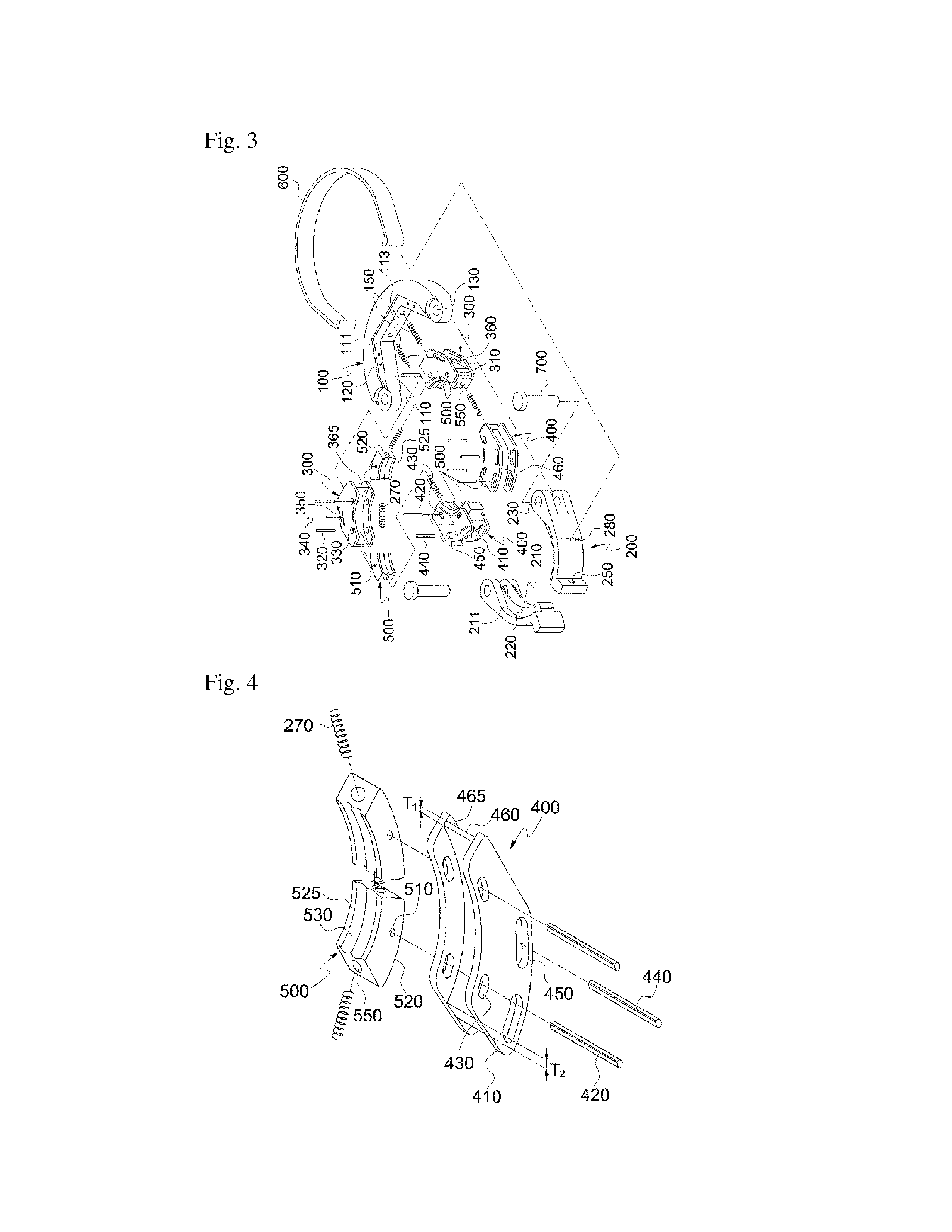
[0032]FIG. 3 is an exploded perspective view showing a pipe fitting and clamping apparatus according to the present invention, FIG. 4 is an exploded perspective view showing an insert and a second insert guide according to the present invention, and FIG. 5 is a cross-sectional view showing a curvature state of a rear surface of a second insert guide according to the present invention.

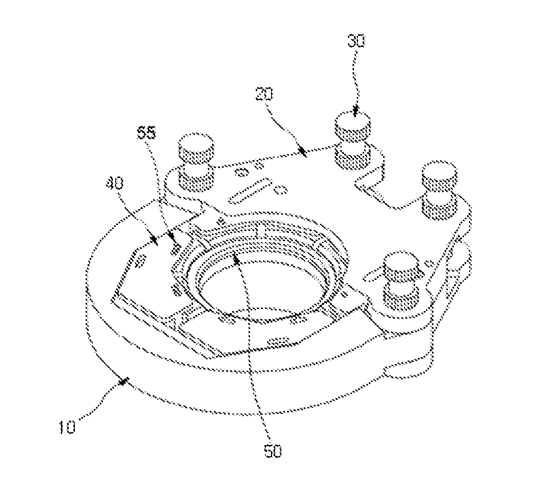
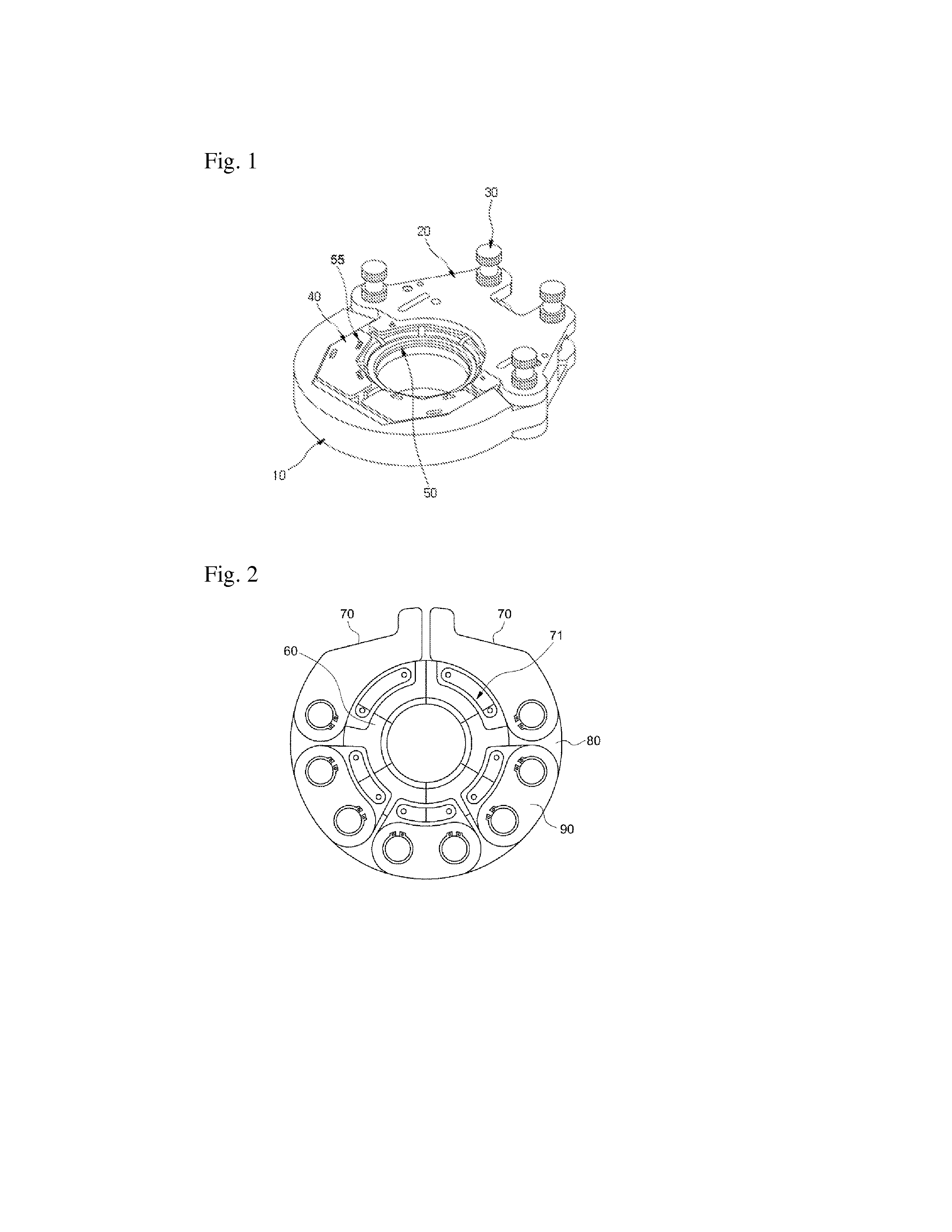
[0033]Referring to FIG. 3, the pipe fitting and clamping apparatus according to the present invention includes a fixed block 100, pivot blocks 200 connected to both of left and right ends of the fixed block 100 to be pivoted, a pair of first insert guides 300 slidably inscribed within the fixed block 100, a pair of second insert guides 400 slidably inscribed within the pivot blocks 200, a plurality of inserts 500 i...


PUM

PropertyMeasurementUnit
diametersaaaaaaaaaa
diametersaaaaaaaaaa
thicknessaaaaaaaaaa

Abstract

Provided is a pipe fitting and clamping apparatus including a fixed block having a first sliding surface with a groove shape formed therein, a pair of pivot blocks pivoted about hinge pins installed at both of left and right ends of the fixed block and having second sliding surfaces rounded at inner sides thereof, a pair of first insert guides installed inside the fixed block and having rear surfaces which come in close contact with the first sliding surface and slide, a pair of second insert guides installed inside the pivot blocks and rounded such that rear surfaces come in contact with the second sliding surface and slide, and a plurality of inserts having front surfaces in contact with outer circumferential surfaces of pipes and rear surface which come in close contact with the front surfaces of the first insert guide and the second insert guide and slide.
According to the pipe fitting and clamping apparatus, since the pivot blocks are connected to both of left and right ends of the fixed block to compress the pipes using the principle of the lever, the compressing force can be increased with a small force during the compressing operation, and since the inserts are slid along the first and second insert guides to surround the entire circumference of the pipes and uniformly apply a pressure thereto upon rotation of the pivot blocks, the pipes can be compressed in a perfect circle shape.

Description

TECHNICAL FIELD[0001]The present invention relates to a pipe fitting and clamping apparatus, and more particularly, to a pipe fitting and clamping apparatus configured to uniformly press the entire circumference of pipes to fit and connect the pipes.BACKGROUND ART[0002]In general, when metal pipes such as stainless steel pipes used for a water supply service and indoor / outdoor pipes of buildings are connected to each other in a longitudinal direction thereof, a metal ring or a rubber ring is interposed in a connecting section, and the connecting section is pressed by a compression tool to maintain airtightness of it.[0003]As described above, a pipe fitting and clamping apparatus for maintaining airtightness of the connecting section is disclosed in Korean Publicized Patent No. 2009-0094908 and Patent Registration No. 10-0762293.[0004]FIG. 1 shows an embodiment of the invention disclosed in Korean Publicized Patent No. 2009-0094908, and FIG. 2 shows an embodiment of the invention dis...

Claims


Application Information

Patent Timeline
Patent Type & Authority Applications(United States)
IPC IPC(8): B23P19/04
CPCB21D39/048Y10T29/53987B25B27/10B23P19/04
Inventor KIM, KWANG CHAN
Owner KIM KWANG - CHAN
Why Eureka
Try Eureka