Mass flow controller verifying system, verifying method and verifying program

a flow controller and verification system technology, applied in the field of mass flow controller verification system, can solve the problems of difficult to accurately calculate the volume of a curved portion, difficult to provide a new addition of piping and chambers, and difficult to accurately calculate the reference volume, etc., to reduce the volume, suppress the thermal influence of the introduction cost, and minimize the effect of the introduction cos

Active Publication Date: 2013-07-11
HORIBA STEC CO LTD
View PDF7 Cites 7 Cited by
  • Summary
  • Abstract
  • Description
  • Claims
  • Application Information

AI Technical Summary

Benefits of technology

The present invention provides a verifying system that can be introduced into an existing gas piping system used in a semiconductor manufacturing process and so forth at a low cost without any change in designing a piping and the like. The verifying system can be easily installed on existing flow gas lines and can verify a mass flow controller based on an accurate reference volume in a short time. The reference volume is formed of the piping, and there is no need of additionally providing a reference volume, which reduces the introduction cost. The reference volume can be set based on the objectives of the verifying process, and it is also possible to set the reference volume every occasion to minimize the volume and shorten the verifying time. The verifying system is reliable and stable, and it can detect abnormalities in a timely manner.

Problems solved by technology

However, in the mass flow controller verifying system as disclosed in Patent Literature 1, some problems are involved as described below.
In some cases, however, it may be difficult to newly provide an additional piping and chamber due to a layout of a factory and the like, and due to the resulting increased costs for designing the piping for the verifying system to fit to the existing piping system and installing of the new piping and chamber.
However, it is difficult to accurately calculate a volume of a curved portion of a piping and a volume inside an open-close valve and so forth, and therefore the calculated value of the reference volume is not very reliable.
If the volume of the chamber is increased to be large or the reference volume is large, an amount of a pressure change required for verifying cannot be measured without a necessary long time lapse.
Therefore, it takes a long time to verify each of the mass flow controllers.

Method used


Image

  • Mass flow controller verifying system, verifying method and verifying program
  • Mass flow controller verifying system, verifying method and verifying program
  • Mass flow controller verifying system, verifying method and verifying program

Examples


Embodiment Construction

[0034]Referring to the attached drawings, an embodiment of the present invention will be described below.

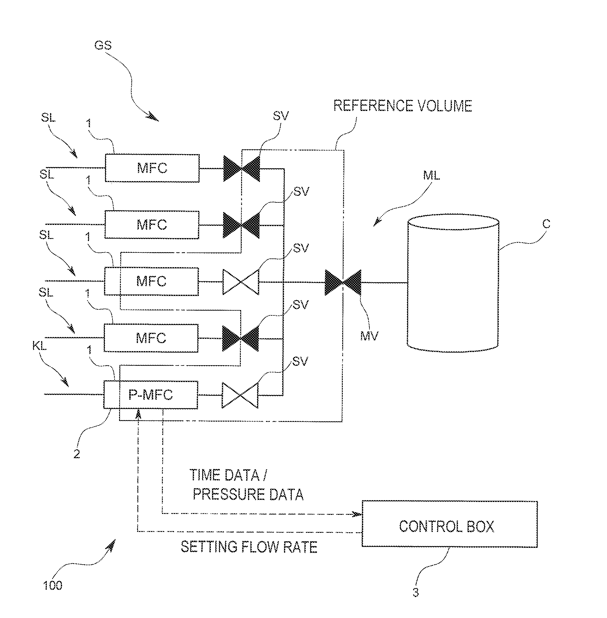
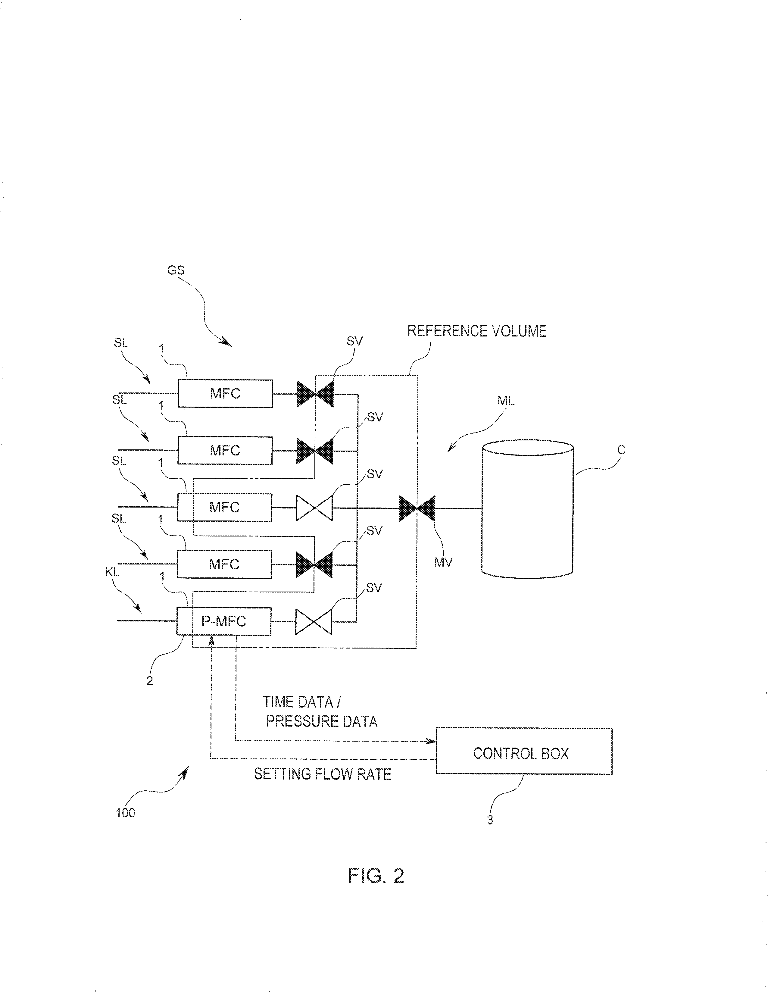
[0035]A verifying system 100 for verifying a mass flow controller (MFC) 1 according to the present embodiment is used for individually verifying a plurality of mass flow controllers 1 provided in an existing gas piping system GS for supplying various kinds of gases from a plurality of gas cylinders (not shown) serving as gas supply means to a process chamber C in a semiconductor manufacturing process and so forth as shown in FIGS. 2 and 3. This gas piping system GS includes a gas box that is provided with a plurality of influent flow gas lines SL in parallel, each of which is connected to the gas cylinder and includes at least the mass flow controller 1 and a secondary side opening / closing valve SV on a downstream of the controller 1, and a post-confluent flow gas line ML that is a gas line formed after the influent flow gas lines SL are joined into one and that includes a post-c...


PUM

PropertyMeasurementUnit
pressureaaaaaaaaaa
volumeaaaaaaaaaa
rough volumeaaaaaaaaaa

Abstract

In a mass flow controller verifying system, there are provided a verifying gas line arranged in parallel to influent flow gas lines and joined into a post-confluent flow gas line, a reference volume calculating portion adapted to calculate a reference volume determined for a specified piping of a gas piping system, a verifying parameter calculating portion adapted to calculate a verifying parameter based on time series data of a measurement pressure measured by a pressure measurement unit during a control of a flow rate by a mass flow controller to be verified, and a comparing portion adapted to compare a reference parameter set based on the reference volume and the verifying parameter, whereby the verifying system can be introduced into an existing gas piping system used in a semiconductor manufacturing process and so forth at a low cost and is capable of verifying a mass flow controller quickly and accurately.

Description

CROSS REFERENCE TO RELATED APPLICATIONS[0001]This application is a continuation of and claims priority to U.S. patent application Ser. No. 12 / 721,433, entitled Mass Flow Controller Verifying System, Verifying Method and Verifying Program, filed Mar. 10, 2010. The entire disclosure of this application is hereby incorporated by reference.BACKGROUND OF THE INVENTION[0002]1. Field of the Invention[0003]The present invention generally relates to a mass flow controller verifying system, and in particular to a method of verifying a mass flow controller in a gas piping system having a plurality of influent flow gas lines including mass flow controllers arranged in parallel, wherein the influent flow gas lines are joined together to form one post-confluent flow gas line.[0004]2. Description of the Background Art[0005]In order to supply a mixed gas to a process chamber in a process of manufacturing a semiconductor and the like, there is constituted a gas piping system that comprises a plurali...

Claims


Application Information

Patent Timeline
Patent Type & Authority Applications(United States)
IPC IPC(8): G01F25/00
CPCG01F1/36G01F1/50G01F25/0053H01L21/67017G01F25/0007G01F25/0038G05B23/00G05B23/02G05D7/0635G01F25/00Y10T137/7759G01F25/15H01L21/67253G01F25/17G01F25/10
Inventor YASUDA, TADAHIROYAMAGUCHI, YUJI
Owner HORIBA STEC CO LTD
Why Eureka
Try Eureka