Electric actuators in aircraft systems

a technology of electric actuators and aircraft systems, applied in the direction of electric generator control, electric devices, machines/engines, etc., can solve the problem that hydraulic actuators may be relatively complex

Inactive Publication Date: 2013-07-18
HAMILTON SUNDSTRAND CORP
View PDF31 Cites 13 Cited by
  • Summary
  • Abstract
  • Description
  • Claims
  • Application Information

AI Technical Summary

Problems solved by technology

The hydraulic actuators may be relatively complex allowing for redundant safeties, and therefore may have multiple wet seals, grommets, hoses, and other components subject to mechanical stresses or wear during flight and which are prone to leakage.

Method used


Image

  • Electric actuators in aircraft systems
  • Electric actuators in aircraft systems
  • Electric actuators in aircraft systems

Examples


Embodiment Construction

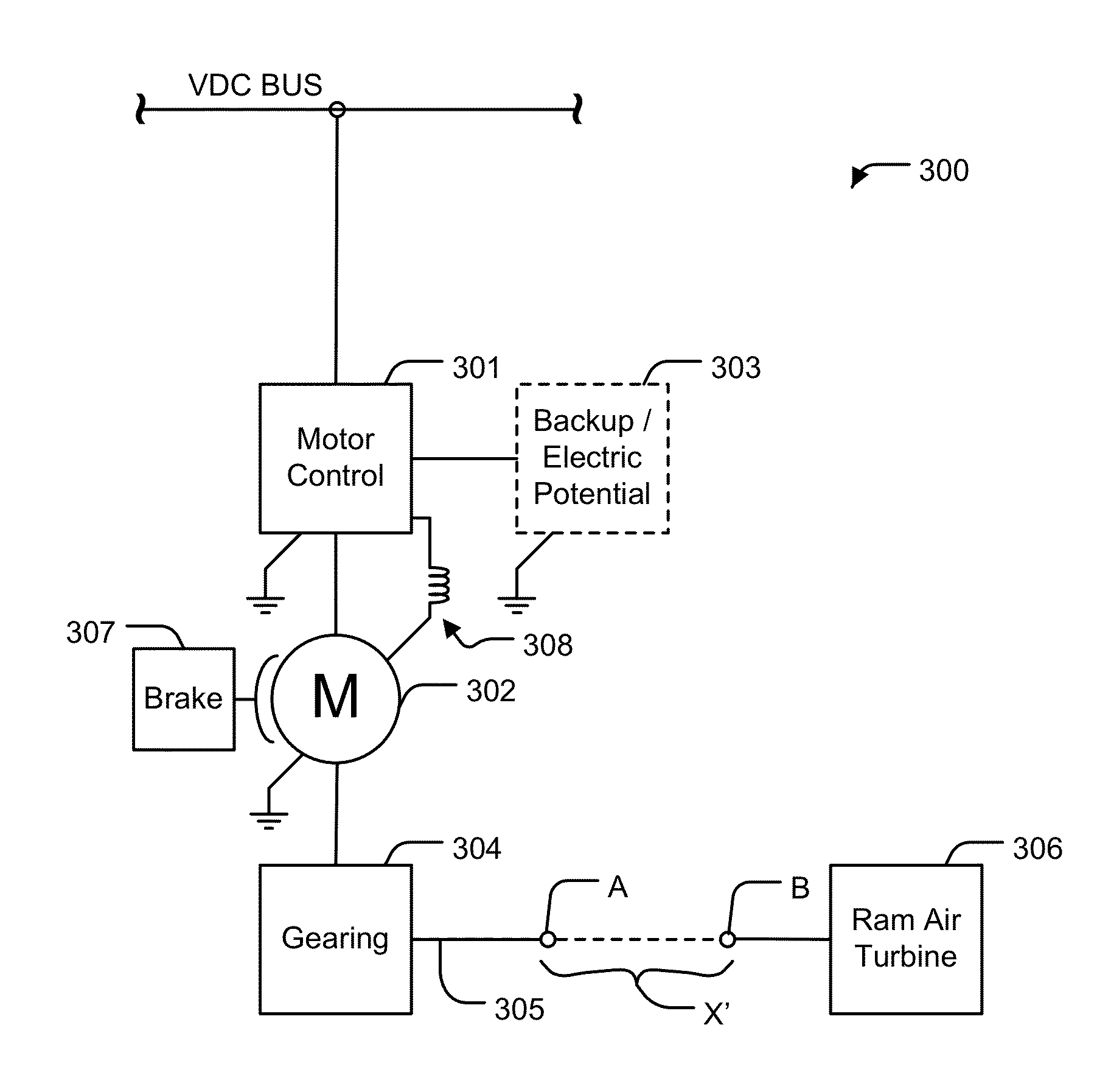
[0010]According to exemplary embodiments of the present invention, an actuation system for emergency aircraft power systems is provided with reduced weight and complexity as compared to conventional systems. The technical effects of one or more of embodiments disclosed herein include eliminating potential for hydraulic leakage, an overall reduced weight of aircraft as well as reduced maintenance tasks and simplifying actuator installation by eliminating hydraulic line connections.

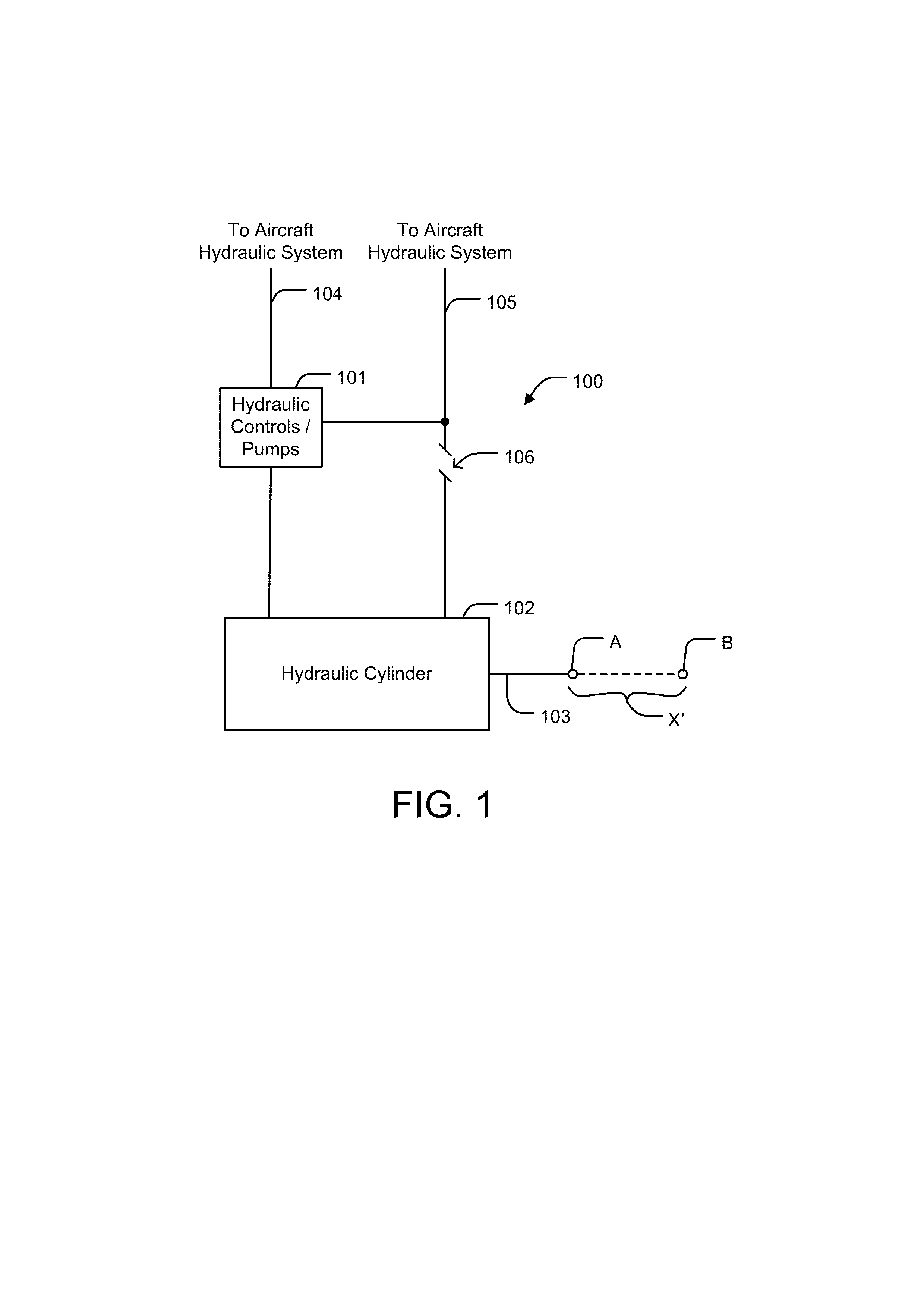
[0011]Turning to FIG. 1, a hydraulic actuator 100 is illustrated. As shown, the actuator 100 includes a plurality of hydraulic controls / valves 101 in communication with a hydraulic cylinder 102 over hydraulic lines 104 and 105. Although not particularly illustrated, it should be understood that a plurality of other components 106 may also form a part of the hydraulic actuator including pressure and stow switches, safety and check valves, snubbing orifices, filler caps, and a plurality of other necessary com...


PUM


Abstract

An electric actuation system for an emergency power system of an aircraft includes a motor control portion, a motor brake, a motor in electrical communication with the motor control portion, mechanical gearing in mechanical communication with the motor, the mechanical gearing configured to translate rotational motion of the motor into linear motion across at least one axis, and an extension member in mechanical communication with the mechanical gearing, the extension member configured to linearly travel across the at least one axis.

Description

BACKGROUND OF THE INVENTION[0001]Generally, the present invention is directed to emergency aircraft systems, and more particularly, exemplary embodiments of the present invention are directed to electrical actuators for mechanically actuating emergency aircraft power systems.[0002]Conventionally, aircraft rely on a ram air turbine (RAT) to provide essential electrical and / or hydraulic power to the aircraft in emergency situations such that power to vital aircraft systems may be adequately maintained. Furthermore, hydraulic actuators are typically used to deploy the RAT outside of an aircraft in these situations. The hydraulic actuators, relying on compressed spring forces and a hydraulic circuit or circuits, may push a RAT into a deployed position in response to an emergency signal or operator request. The hydraulic actuators may be relatively complex allowing for redundant safeties, and therefore may have multiple wet seals, grommets, hoses, and other components subject to mechanic...

Claims


Application Information

Patent Timeline
Patent Type & Authority Applications(United States)
IPC IPC(8): B60L1/00H02P9/08H02K7/102H02K7/18B64D41/00H02K7/116
CPCB60L8/006B60L2200/10Y02T10/7083Y02T50/44Y02T90/16B64D41/007Y02T10/7072Y02T50/40
Inventor LARSON, MICHAEL E.SASSCER, GARY
Owner HAMILTON SUNDSTRAND CORP
Why Eureka
Try Eureka