Testing protection schemes of a power converter

a technology of protection scheme and power converter, which is applied in the direction of power supply testing, instruments, measurement devices, etc., can solve problems such as bringing down the system

Inactive Publication Date: 2013-07-18
IBM CORP
View PDF17 Cites 30 Cited by
  • Summary
  • Abstract
  • Description
  • Claims
  • Application Information

AI Technical Summary

Problems solved by technology

If the common bus is exposed to an input fault for a prolonged peri...

Method used


Image

  • Testing protection schemes of a power converter
  • Testing protection schemes of a power converter
  • Testing protection schemes of a power converter

Examples


Embodiment Construction

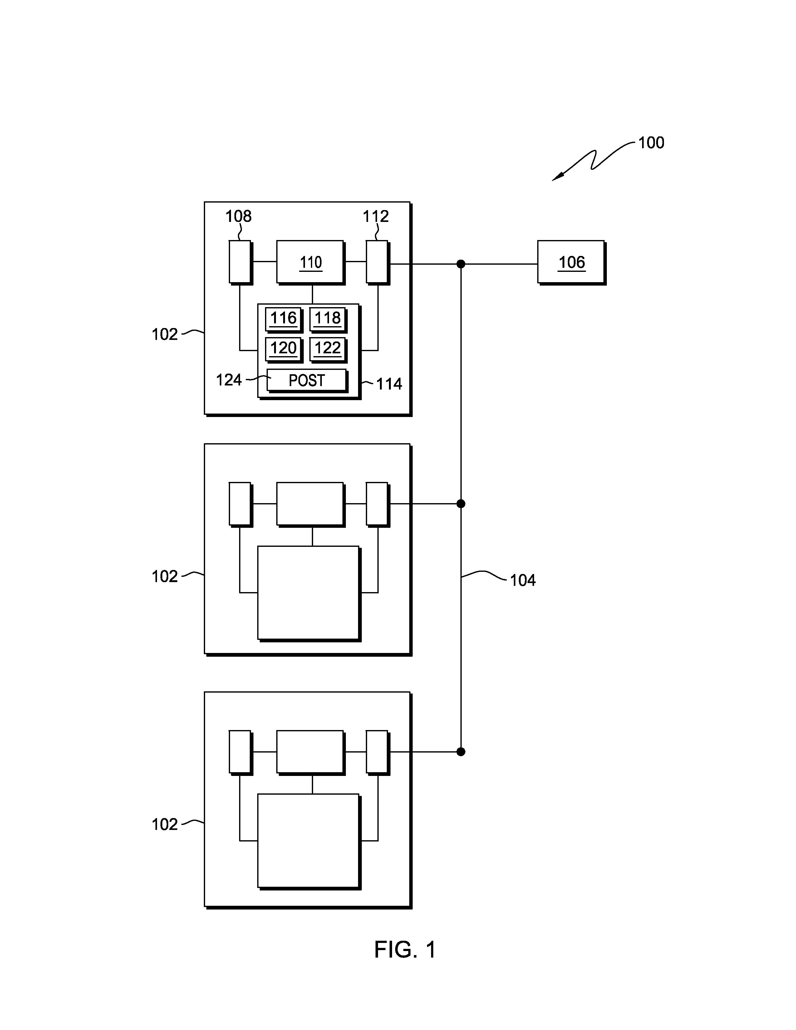
[0016]The present invention will now be described in detail with reference to the Figures. FIG. 1 illustrates a redundant power supply system, generally designated 100, according to one embodiment of the present invention.

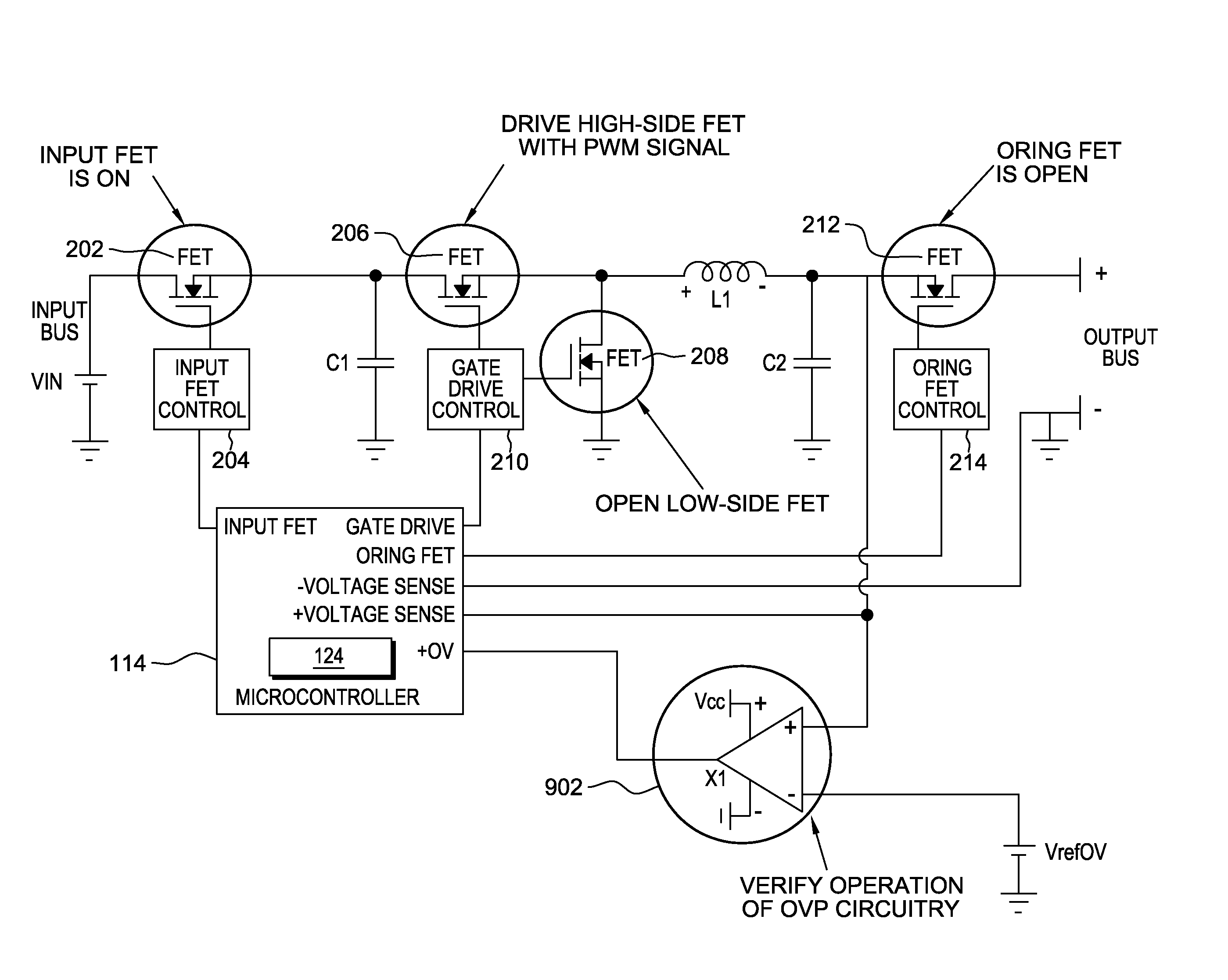
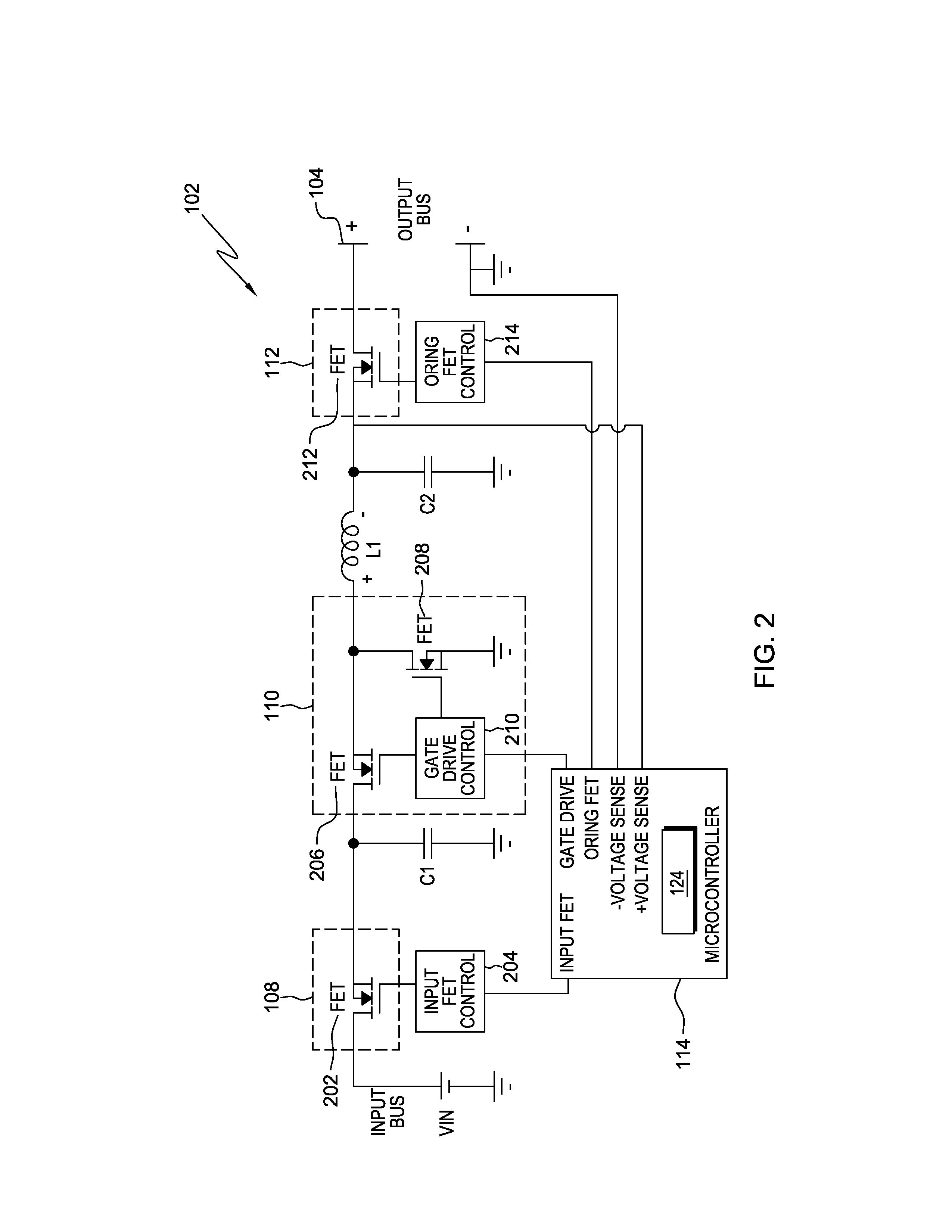
[0017]Redundant power supply system 100 includes a plurality of redundant power supply modules 102. A power supply module (also known as a power converter) is a buffer circuit that provides power with the characteristics required by a load, from a primary power source with characteristics incompatible with the load. This might include AC to DC conversions and DC to DC conversions (converting a source of direct current from one voltage level to another). In short, a power supply module makes the load compatible with its power source. In the embodiment illustrated in FIG. 1, each power supply module 102 is connected to a common bus 104. Common bus 104, which may also be referred to as the output bus, is connected to load 106.

[0018]Each respective power supply module ...


PUM


Abstract

A system for testing the existing protection schemes of a power converter. The system simulates the voltage regulator producing a voltage level below an under-voltage threshold. The system simulates the voltage regulator producing a voltage level above an over-voltage threshold. The system simulates a short in the power converter pulling down the input bus. The system simulates a short in the power converter pulling down the output bus. The system measures the system responses to these simulations against responses of a properly operating system and determines if the power converter's protection schemes are operating correctly.

Description

FIELD OF THE INVENTION[0001]The present invention relates generally to protecting a load from a malfunctioning power converter and more particularly to testing existing protection schemes for the power converter.BACKGROUND OF THE INVENTION[0002]In a redundant power supply system, two or more power supply modules (power converters that convert electrical power from one form into another) have respective outputs connected in parallel to a single load via a common bus. Each power supply module has an associated ORing element (or switch), typically a field-effect transistor (FET) device, disposed between the output node of each module and the load. The ORing switches are operable to selectively couple or decouple the respective power supply module from the load, thereby effectively isolating current generated at the corresponding module from passing to the common bus. Similarly, each respective power supply module may have an associated input switch connecting the module to a power sour...

Claims


Application Information

Patent Timeline
IPC IPC(8): G01R31/28
CPCG01R31/40
Inventor EGAN, PATRICK K.HRUBY, BRIAN J.MILLER, MICHAEL L.
Owner IBM CORP
Why Eureka
Try Eureka