Radar system, transponder device, method for radar processing and computer readable media

Active Publication Date: 2013-07-18
FURUNO ELECTRIC CO LTD
View PDF10 Cites 10 Cited by
  • Summary
  • Abstract
  • Description
  • Claims
  • Application Information

AI Technical Summary

Benefits of technology

[0023]According to the above aspects of the invention, in the case where the radar classification of the radar transceiving device is the solid-state radar, when the radar transceiving device transmits the electromagnetic wave at the first frequency and the transponder device receives the electromagnetic wave transmitted from the radar transceiving device, the radar transceiving device transmits the response wave at the second frequency different from the first frequency, the radar tr

Problems solved by technology

For this reason, the displayed Morse code indicating the racon is elongated in distance directions on the PPI screen, causing a problem that the Morse code is collapsed.
Therefore, the Morse code displayed on the PPI screen is adversely elongated in the distance directions (both in a shorter distance d

Method used


Image

  • Radar system, transponder device, method for radar processing and computer readable media
  • Radar system, transponder device, method for radar processing and computer readable media
  • Radar system, transponder device, method for radar processing and computer readable media

Examples


Embodiment Construction

[0037]Below, several suitable embodiments of a radar system, a transponder device, a method for radar processing, and a radar processing program according to the present invention are described in detail with reference to the accompanying drawings. In the embodiments, the present invention is applied to a ship radar system that uses a pulse compression radar as one example of a solid-state radar, and displays locations of surface ships on a PPI screen.

Ship Radar System

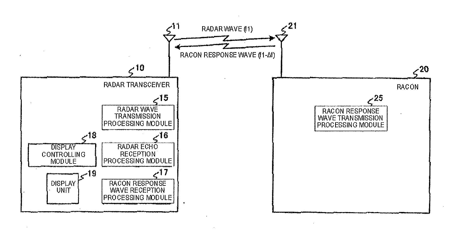
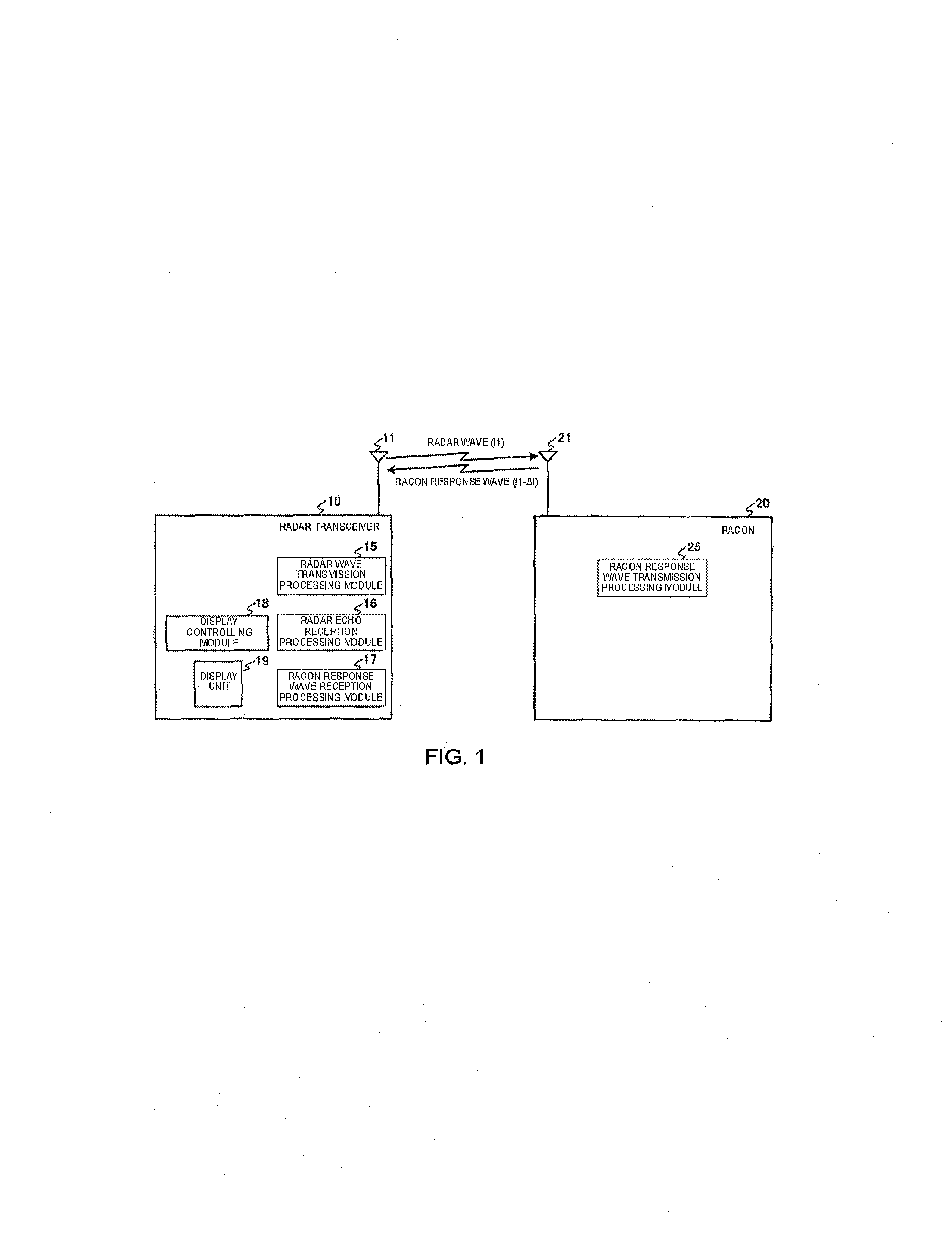
[0038]First, the ship radar system according to one embodiment of the invention is described. FIG. 1 is a schematic diagram illustrating the ship radar system according to this embodiment. The radar transceiver 10 is a pulse compression radar in this embodiment.

[0039]In the ship radar system shown in FIG. 1, the radar transceiver 10 equipped in a ship transmits radar waves at a frequency f1, throughout all directions around the ship (360°). The radar transceiver 10 receives a radar echo at the same frequency f1 which i...


PUM


Abstract

A radar system is provided. The system includes a radar transceiving device equipped in a movable body and for transmitting an electromagnetic wave at a first frequency, and a transponder device arranged in a beacon and for transmitting a response wave upon receiving the electromagnetic wave. The transponder device includes a response wave transmitting module for transmitting, when a radar classification of the radar transceiving device is a solid-state radar, a response wave at a second frequency different from the first frequency in response to receiving the transmitted electromagnetic wave. The radar transceiving device includes a transmitting module for transmitting the electromagnetic wave, a receiving module for receiving a radar echo at the first frequency and the response wave at the second frequency, and a display controlling module for displaying, on a predetermined radar display unit, locations of the beacon and another movable body existing around the movable body.

Description

CROSS-REFERENCE TO RELATED APPLICATION(S)[0001]The application claims priority under 35 U.S.C. §119 to Japanese Patent Application No. 2012-3963, which was filed on Jan. 12, 2011, the entire disclosure of which is hereby incorporated by reference.TECHNICAL FIELD[0002]The present invention relates to a radar system, such as a ship radar system capable of controlling to appropriately and efficiently display other movable bodies and / or transponder devices on a display unit when a solid-state radar is adopted in a radar transceiver. The present invention also relates to a transponder device, a method for radar processing, and a computer readable media, utilizing this technology.BACKGROUND OF THE INVENTION[0003]Conventionally, surface ships are required to accurately acquire locations of the ship and other ships when traveling on major routes close to narrow water channels or land (or shore). Therefore, radar transceivers are equipped in the ships, while route buoys containing radar beac...

Claims


Application Information

Patent Timeline
IPC IPC(8): G01S13/75G01S13/937
CPCG01S13/753G01S13/9307G01S13/787G01S13/767G01S13/937
Inventor KOJIMA, TATSUYAYAMABAYASHI, JUN
Owner FURUNO ELECTRIC CO LTD
Why Eureka
Try Eureka