
Operation input apparatus, operation input method, and program

Active Publication Date: 2013-07-18
SHIMANE PREFECTURAL GOVERNMENT MATSUE
View PDF10 Cites 47 Cited by
  • Summary
  • Abstract
  • Description
  • Claims
  • Application Information

AI Technical Summary

Benefits of technology

The patent aims to improve the accuracy of motion input on a display by reducing the likelihood of incorrect recognition and minimizing the burden on the operator. This can be achieved by providing a more efficient and reliable method for detecting and responding to operator actions.

Problems solved by technology

However, in actually existing technologies, satisfaction has not been obtained for a gesture operation and the like without using apparatuses such as a mouse, a keyboard, a touch panel and the like, because of such drawbacks as: necessity of a non-intuitive complex motion; physical burden imposed in performing an exaggerated motion; low visibility of an operation object screen caused by an operator oneself due to the hand in use of an operation as seen in PTL2; and erroneous recognition attributed to ambiguity of “connection” between motions of an gesture operation.
However, it can be concluded that implementation thereof is quite difficult due to: a drawback of visibility that an object screen is covered with the hand itself in use of an operation; and a drawback that two operational steps from “selection” to “determination” are not clearly distinguished.

Method used


Image

  • Operation input apparatus, operation input method, and program
  • Operation input apparatus, operation input method, and program
  • Operation input apparatus, operation input method, and program

Examples


Embodiment Construction

[0061]Various embodiments are described below with reference to the drawings.

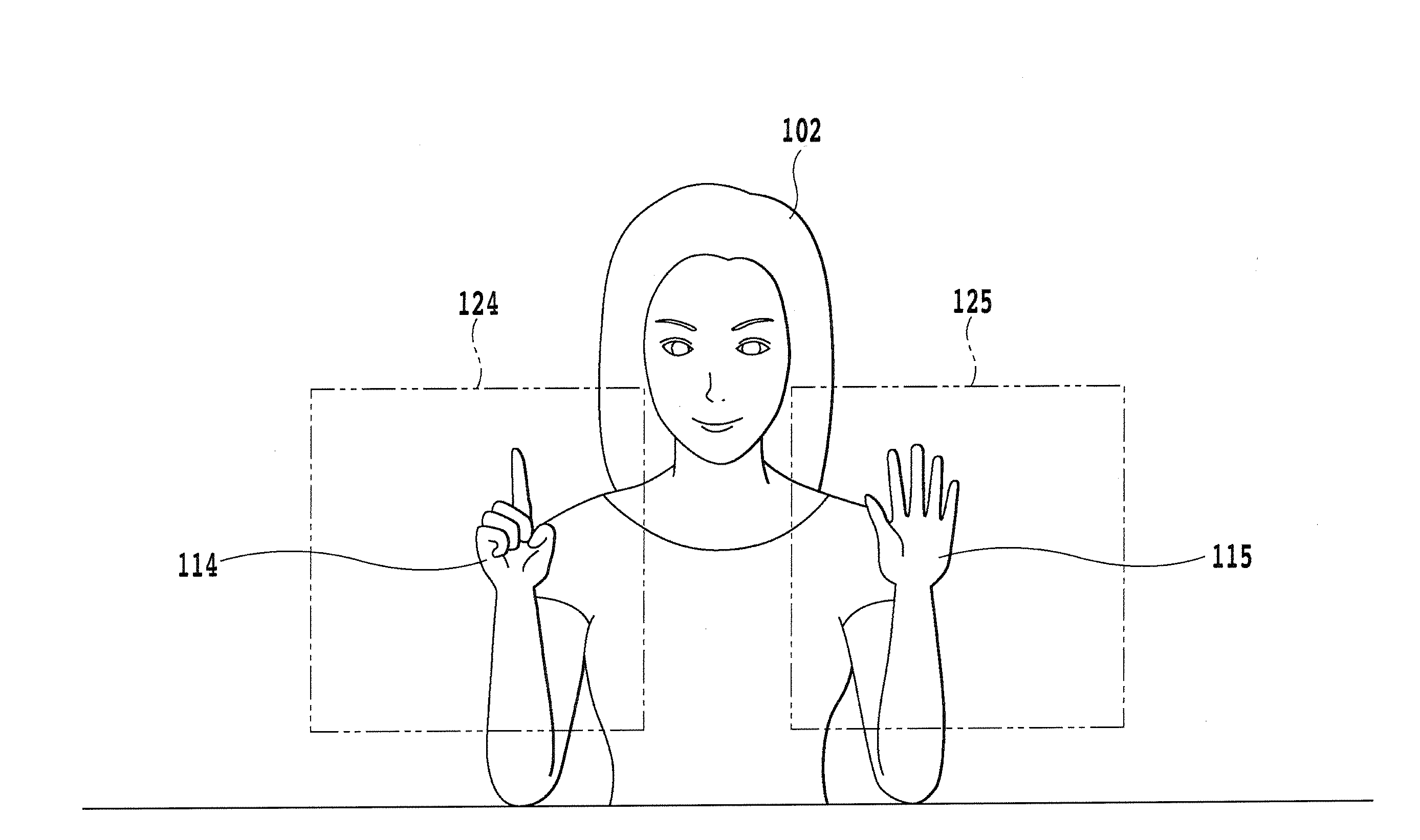
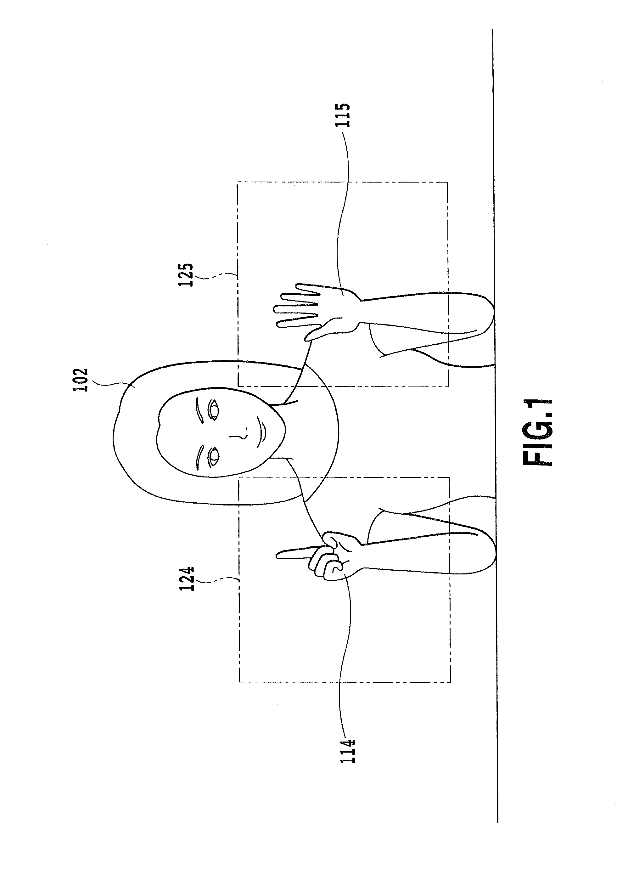
[0062]FIG. 1 is a diagram showing an example of an operation input system. In the illustrated embodiment, as described below, a right side area 124 and a left side area 125 are respectively defined as an operation area for a right hand 114 and that for a left hand 115 with reference to the head of an operator 102, and respective operation contents are determined and processed as operation inputs. As is understandable with reference to FIG. 1, through the arrangement of the right side area 124 and the left side area 125 at a certain distance, such an arrangement may prevent motions of the right hand 114 and the left hand 115 of the operator being conflated and / or erroneously recognized.

[0063]By thus defining the two areas, in at least certain embodiments different types of operations may be performed with the right hand 114 and the left hand 115 in face of a display 111 as shown in FIG. 20, and thereby, oper...


PUM


Abstract

A motion input is appropriately identified. A display is disposed in front of an operator, and a motion, performed by the operator within ranges set in predetermined right and left positions between the operator and the display, is identified. In certain circumstances, the shape of a finger of the operator may be handled as an object of an operational determination.

Description

TECHNICAL FIELD[0001]The current disclosure is generally related to an operation input apparatus and an operation determining method, and in particular, to determining a motion of a measured object based on an image, such as an image captured by a video camera or in another manner.BACKGROUND[0002]In recent years, various input methods have been employed for computers, game machines and the like. For example, a system has been proposed which recognizes a motion of an operator such as a predefined gesture through the imaging thereof using a camera or the like and determines to which of operational contents the gesture corresponds. For example, PTL1 proposes a technology of enabling a very easy and convenient apparatus operation without necessity of an input apparatus such as a mouse, and the technology includes: a host computer recognizing the shape and the motion of an object in an image imaged by a CCD camera; and a display displaying the shape and the motion of the object recognize...

Claims


Application Information

Patent Timeline
IPC IPC(8): G06F3/01
CPCG06F3/017G06F3/011G06F3/0482G06F3/04817G06F3/04842G06F3/0304G06F3/0346G06F3/0487G06F3/16G10L15/005G06V40/20
Inventor IZUMI, KENJI
Owner SHIMANE PREFECTURAL GOVERNMENT MATSUE
Learn More