Pooling of an antenna and of a converter for supplying power to an electronic circuit

Inactive Publication Date: 2019-06-27
COMMISSARIAT A LENERGIE ATOMIQUE ET AUX ENERGIES ALTERNATIVES
View PDF0 Cites 1 Cited by
  • Summary
  • Abstract
  • Description
  • Claims
  • Application Information

AI Technical Summary

Benefits of technology

[0008]The invention aims to rectify the abovementioned drawbacks of the prior art, and it aims to propose, more particularly, a compact and less burdensome

Problems solved by technology

These biocell systems are therefore particularly bulky.
Furthermore, beyond marine applications, the electronic com

Method used


Image

  • Pooling of an antenna and of a converter for supplying power to an electronic circuit
  • Pooling of an antenna and of a converter for supplying power to an electronic circuit
  • Pooling of an antenna and of a converter for supplying power to an electronic circuit

Examples


Embodiment Construction

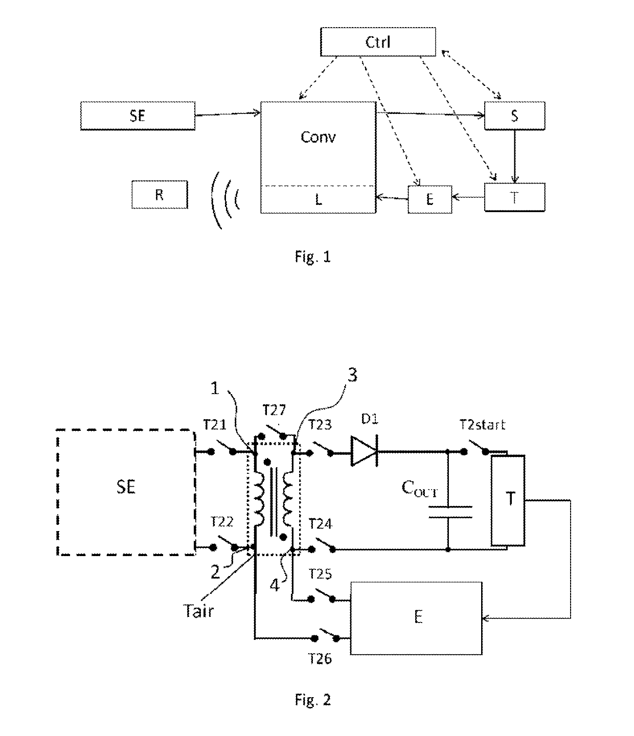
[0029]FIG. 1 shows a diagram illustrating the principle of the invention. An energy source SE produces electrical energy, which is recovered by a converter Conv that comprises at least one inductive element L for converting electrical energy. The energy delivered by the converter is stored in a storage means S. When there is enough energy stored in S, an electronic processing circuit T is supplied with energy so as to perform a predefined function, for example perform a measurement using sensors or indicate an identifier. The electronic processing circuit T then supplies data, for example measurement data, to an emission circuit E, which then sends these data by wireless communication to a receiver R. According to one aspect of the invention, the emission circuit E uses all or part of the inductive element L of the converter as an antenna for sending the data. This pooling of the inductive element L thus makes it possible to no longer have an antenna separate from the inductive elem...


PUM


Abstract

An autonomous electronic system includes two input terminals that are connected to an external electrical energy source, a converter circuit comprising at least one inductive element and connected to the terminals in order to receive energy from the source, a means for storing the energy delivered by the converter circuit, an electronic processing circuit performing a predefined function and delivering a data signal after performing the function, an emission circuit connected to an antenna in order to transmit the data signal to a remote receiver, and a control circuit able to control the circuits supplied with power by virtue of the energy source, the system being wherein the converter circuit and the antenna comprise at least one common inductive element and in that it comprises a link device situated between the emission circuit and the at least one common inductive element so as to transmit the signal emitted by the antenna formed at least partly by the at least one common inductive element.

Description

CROSS-REFERENCE TO RELATED APPLICATIONS[0001]This application claims priority to foreign French patent application No. FR 1763119, filed on Dec. 22, 2017, the disclosure of which is incorporated by reference in its entirety.FIELD OF THE INVENTION[0002]The invention belongs to the field of autonomous electronic systems comprising an electronic circuit intended to regularly transmit data to a remote receiver.BACKGROUND[0003]An autonomous electronic system is capable of recovering, in its environment, the electrical energy that it needs to perform the function for which it is predefined (measuring an environmental parameter, signalling its presence by sending an identifier, etc.) and communicate wirelessly with a remote receiver. Such systems are used for example in IOT systems. The autonomous electronic system may be connected to various types of electrical energy source that draw their electrical energy from a chemical, mechanical, solar, thermal energy source, etc.[0004]Such autonom...

Claims


Application Information

Patent Timeline
IPC IPC(8): H01Q7/06H01Q9/42
CPCH01Q7/06H01Q9/42H01Q1/44H01Q7/00H02J50/10H02J7/00712G05F7/00H01F38/12H01F2038/143H04B1/44
Inventor WANDEROILD, YOHANCAPITAINE, ARMANDEMOREL, ADRIENPILLONNET, GAEL
Owner COMMISSARIAT A LENERGIE ATOMIQUE ET AUX ENERGIES ALTERNATIVES
Why Eureka
Try Eureka